English ![]()

No. 7, Tianyang 6th Road, Dongfang Community, Songgang Street, Bao'an District, Shenzhen, Guangdong, China(518100)
Views: 164 Author: Site Editor Publish Time: 2026-08-17 Origin: Site
Why choose CNC for custom parts? You gain repeatability across batches. You access diverse materials. You produce complex geometries without manual intervention. This approach outperforms traditional methods.
Computer numerical control eliminates human error. The machine follows programmed paths. Your design becomes reality with tight tolerances. Quality remains consistent throughout production.
This article explains the Custom CNC Machining Workflow. You will learn each stage. You will understand how CNC machined parts come to life. We compare CNC Machining vs 3D Printing for Production. We also provide a Precision CNC Machining Services Guide. CNC Manufacturing Services for Custom Parts require careful planning. Machining demands attention to detail. Manufacturing excellence starts with proper setup.
CNC machining uses computer-controlled tools to cut parts from solid blocks with high precision.
Design for manufacturability (DFM) feedback helps cut costs and shorten lead times.
CAM software turns 3D models into G-code, which tells the machine how to move.
Good workholding and toolpath selection ensure accuracy and efficiency.
Finishing treatments and quality checks make sure parts match the required specs.
Every custom part starts as a digital 3D model. You build this model with CAD (Computer-Aided Design) software like SolidWorks or NX. The model captures every size, feature, and surface of your part. You must include all key details in this digital file. The CNC machine will follow this model exactly. Any mistake in your design will show up in the final part.
Your CAD model acts as the guide for everything that comes next. You need to design with manufacturing in mind from the start. Follow these key practices when building your model:
Use standard tooling sizes – Design internal fillets and holes to match common end mill diameters. This cuts programming time and machining cost.
Design within standard material sizes – For example, design a shaft to 29mm diameter so you can machine it from a standard 30mm rod. This lowers material removal and waste.
Reduce fixturing setups – Design parts that need fewer repositioning steps. Each re-fixturing adds time and cost to your project.
Consider tool reach – Keep hole depth-to-diameter ratios below 10:1. Deep, narrow features cause tool deflection and possible collisions.
Simplify geometry – Avoid undercuts and deep pockets when possible. Use symmetry for easier fixturing.
A service provider can offer design-for-manufacturability (DFM) feedback at this stage. Their engineers review your model and suggest improvements. This teamwork prevents costly redesigns later.
Your material choice directly affects cost, machinability, and part performance. Aluminum offers great machinability and lightweight strength. Stainless steel provides corrosion resistance for tough environments. Titanium delivers excellent strength-to-weight ratio for aerospace and medical uses. Brass machines easily and suits electrical components. Plastics like POM (Delrin) offer high precision with low friction.
| Material | Key Properties | Common Applications |
Aluminum | Lightweight, strong, corrosion-resistant, excellent machinability | Aerospace, automotive, medical, consumer products |
Stainless Steel | Strong, corrosion-resistant, grades vary for machinability | Surgical equipment, shafts, gears, industrial machinery |
Titanium | Tough, strong, biocompatible, corrosion-resistant | Medical implants, aerospace, military components |
Brass | Durable, easily machinable, electrically conductive | Plumbing, electrical components, musical instruments |
POM (Delrin) | High machinability, low friction, dimensional stability | Precision parts, gears, bushings |
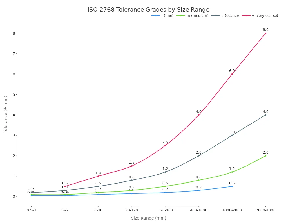
Tolerances define how much variation you allow in each dimension. ISO 2768-1 sets four tolerance classes: fine (f), medium (m), coarse (c), and very coarse (v). You should apply tight tolerances only to critical functional surfaces. Over-specifying tolerances increases machining time and cost without adding value.
DFM feedback helps you optimize your design for cnc manufacturing. Common recommendations include relaxing non-critical tolerances, increasing internal radii to match standard tooling, and selecting more machinable materials. One documented case study showed that redesigning sharp internal corners to fillets eliminated secondary EDM finishing. This change reduced lead time by 20% for a custom CNC-machined metal bracket.
Your design phase determines the success of your entire cnc machining project. Careful planning here reduces costs, shortens lead times, and ensures your part meets every specification. The next stage converts your optimized design into machine instructions.
Your CAD model holds all the shape details your part needs. But a CNC machine can't read a CAD file directly. It needs a different language. That language tells the machine where to go, how fast to cut, and which tool to use. CAM software handles this translation.
CAM means Computer-Aided Manufacturing. This software takes your 3D model and turns it into instructions the machine can follow. Think of CAM as a translator between your design and the machine. Without it, your CNC project would stop before it even begins.
Mastercam is the most popular CAM software in the industry. More than 450,000 users in over 100 countries use it every day. It has led the field for over 40 years. Its advanced tools include Dynamic Motion Technology and AI-powered features. These help programmers create smart cutting plans for custom parts.
CAM software does more than just write code. It looks at your part's shape and material. Then it picks the best machining method on its own. This automation speeds up the whole design-to-production process. Programmers can focus on fine-tuning instead of writing code by hand.
Optimized toolpaths bring real benefits. Machining time drops by 15–30% with smart path planning. Material savings reach 5–12% by cutting less waste. These improvements also make tools last longer. Every custom part gains from this efficiency.
G-code is the standard language for CNC machines. It started with early numerical control systems. Today it's still the universal way to give instructions to machines everywhere.
A single G-code block combines several commands. For example, a line might specify a linear move, feed rate, tool selection, and spindle speed. Each part controls a specific action.
G-codes handle movement tasks, such as rapid positioning and linear feed. M-codes control auxiliary actions like spindle on/off, coolant, and tool changes. Together, G-codes and M-codes work as a team. G-codes move the machine. M-codes manage everything around that movement.
Toolpath strategy matters a lot for custom parts. Each unique design needs a unique approach. CAM software offers various strategies optimized for different geometries and materials.
Simulation allows testing of toolpaths before production, reducing the risk of errors.
This programming stage decides your part's final quality. Good toolpath selection cuts machining time and material waste. Accurate G-code ensures the machine cuts exactly as designed. The next phase brings your custom part to life on the shop floor.
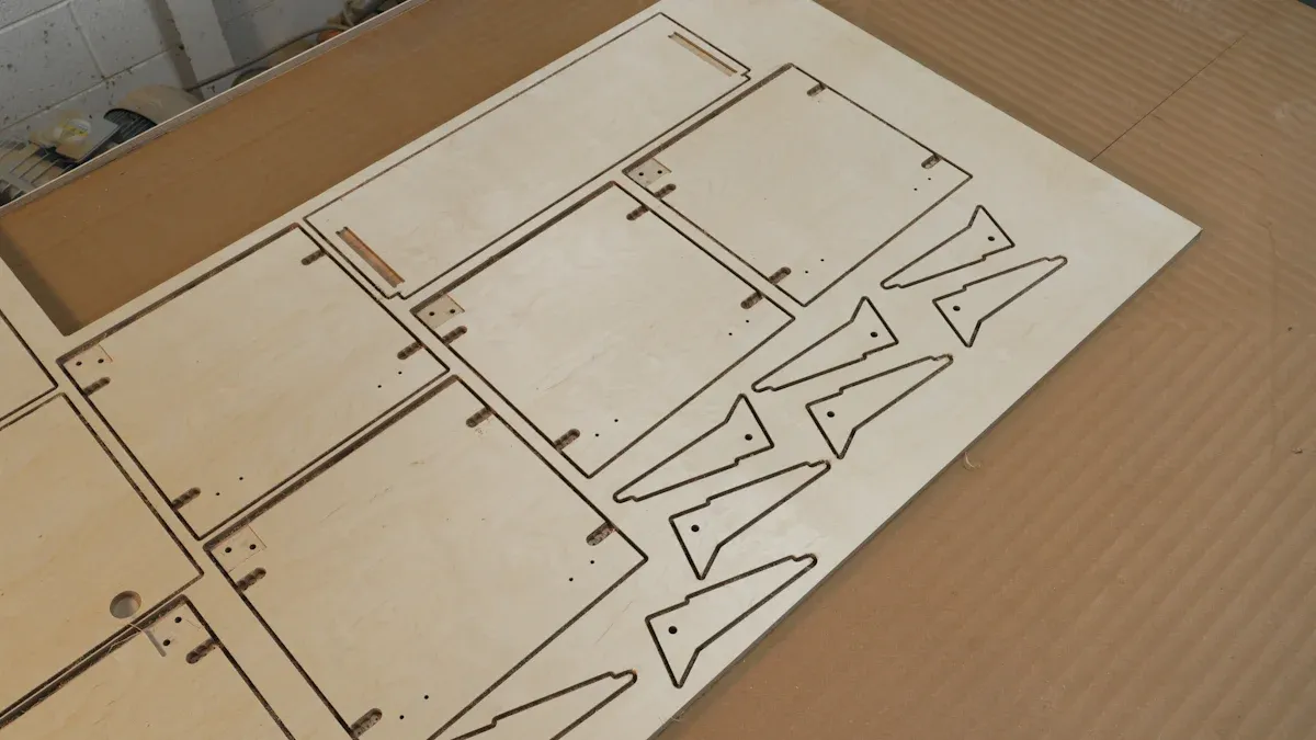
CNC machining is a subtractive process. You start with a solid block of material, called a billet, and remove what you don't need. Computer-controlled cutting tools carve away excess material until only your custom part remains. This approach gives you complete control over the final shape, unlike additive methods that build parts layer by layer.
Before any cutting begins, you must secure your material. The machine cannot hold the billet itself. You need a workholding system that keeps the part rigid and positioned correctly. The right choice depends on your part's size, shape, and material.
| Method | Rigidity | Setup Speed | Best For | Limitations |
| Mechanical Vise & Clamps | Depends on design | Depends on design | Rigid parts | May deform thin walls |
Modular Fixture | Depends on design | Depends on design | Multi-part production | Trade-off in rigidity |
Dedicated Fixture | Depends on design | After setup, efficient | High-volume production | High upfront cost |
Vacuum Workholding | Depends on design | Depends on design | Thin plates | Limited force resistance |
Magnetic Workholding | Depends on design | Depends on design | Ferrous flat parts | Not for non-ferrous |
Mechanical vises are common for many parts. Soft jaws can be used for irregular shapes. Vacuum workholding works for thin or fragile parts. Magnetic workholding is suitable for ferrous flat parts.
Modular fixturing has improved setup times. Workholding systems are now more modular, allowing faster changes. This reduces setup time and improves process consistency.
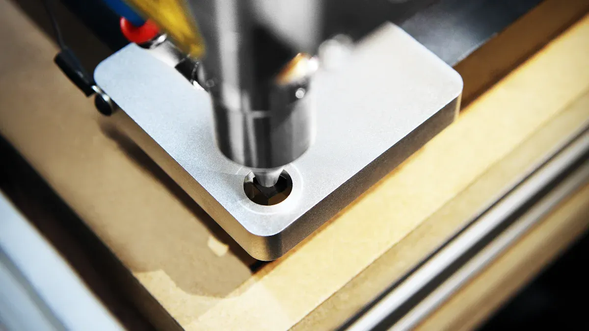
Once your material sits securely, the cutting begins. Three primary operations handle most custom parts: milling, turning, and drilling.
CNC milling uses a rotating cutting tool against a stationary workpiece. Multi-axis vertical machining centers excel at flat surfaces, pockets, contours, and complex 3D geometries. You get versatility for non-cylindrical, multi-surface parts like brackets, housings, and molds. CNC turning rotates the workpiece against a stationary tool to create round or conical shapes. Shafts, bolts, bushings, and pins benefit from turning's excellent concentricity and surface finish. The rule of thumb: if it's round, turn it. If it's any other shape, mill it.
| Aspect | CNC Turning | CNC Milling |
| Core Motion | Workpiece rotates | Cutting tool rotates |
Ideal Geometry | Cylindrical, symmetric shapes | Flat surfaces, pockets, contours, complex 3D geometries |
Typical Applications | Round components | Non-cylindrical components |
Key Advantage | Excellent concentricity and surface finish | Versatility for non-cylindrical, multi-surface parts |
Advanced 5-axis machines can achieve high precision, enabling complex custom parts with superior surface finishes. Standard precision is also very tight. These machines offer significant cost efficiency in low-volume production. By drastically reducing the number of setups, they minimize labor costs, tooling changes, and fixture requirements—factors that dominate cost structures in small batch production. This makes them ideal for prototyping custom parts, R&D applications, and one-off builds where fast turnarounds and accuracy are critical.
The additional A and B axes bring material closer to the tool. Shorter cutting tools resist vibration better, producing finer finishes. All milling operations for complex geometries complete in one setup, reducing operational costs and errors common in 3-axis machining. You machine the most complicated angles with tighter tolerances, and drilling reaches tighter, more complex angles with finer finishes. This cnc machining process delivers the precision and quality your custom parts demand.
After cutting is done, your custom part still needs more work. The raw surface may have tool marks or may not be strong enough. Surface treatments fix these issues. They make the part work better and look better.
Surface finishing turns your part from something functional into a finished product. Different treatments do different jobs. The table below shows common options and what they are best for.
| Surface Treatment | Description | Common Applications |
| Anodizing | Process for aluminum | Various |
Powder Coating | Dry powder coating | Various |
Electroplating | Metal layer deposition | Various |
Bead Blasting | Mechanical texturing | Various |
Polishing | Smoothing surface | Various |
Anodizing is very important for aluminum parts. The oxide layer creates a hard, scratch-resistant surface that also resists corrosion. You can add colors during this process too. This treatment keeps aluminum light while making it much stronger.
Your finish choice depends on where the part will be used. Medical devices need smooth, clean surfaces. Outdoor equipment needs protection from rust and weather. Consumer products benefit from nice colors and textures. Some service providers offer a variety of finishing options.
Quality control starts before machining and continues through final checks. You need to be sure every measurement meets your specs. Precision tools make this possible.
Coordinate measuring machines (CMMs) give the most complete analysis. These devices measure points on x, y, and z axes to provide detailed geometric data. They check parts without damaging them, gathering shape data to quickly find structural flaws. Modern CMMs work with 3D CAD models, allowing direct comparison of real measurements to your digital design.
CMMs provide high measurement accuracy, allowing detection of deviations early in production, reducing scrap, rework, and downtime.
Micrometers and calipers handle simpler measurements. Standard procedures ensure reliable results.
Statistical process control (SPC) adds another layer of protection. Control charts monitor individual measurements and detect process shifts. This approach separates normal variation from real problems like broken tools or miscalibration. You act only when the data demands action. This prevention-based method reduces defects before they happen.
Some service providers perform checks from design to final inspection. Their in-house team uses CMMs, micrometers, and other precision tools. Every custom part receives thorough verification against your specifications. This commitment to quality ensures your part performs exactly as designed.
Your custom part journey follows a clear path: CAD design, CAM programming, subtractive machining, then finishing and inspection. This computer numerical control workflow delivers parts that meet every specification.
CNC machining beats 3D printing for precision work. You achieve tighter tolerances than 3D printing, with better surface finish and material strength. Material choices span aluminum, stainless steel, titanium, plastics, and composites. CNC machined parts keep full material strength, unlike layered prints.
Consider CNC manufacturing for your next project. Contact a service provider for a competitive quote and design-for-manufacturability feedback. Their engineers will optimize your design for cost-effective CNC machining production. This manufacturing approach delivers the quality you need.
Lead times depend on part complexity, material, and quantity. Simple prototypes may finish in days. Complex 5-axis parts with tight tolerances take longer. Service providers optimize processes to reduce lead times without sacrificing quality. Request a quote for an accurate timeline.
Standard CNC machining holds tight tolerances. Advanced 5-axis machines achieve even tighter tolerances. You should specify tight tolerances only on critical surfaces. Relaxing non-essential tolerances reduces cost and machining time significantly.
Aluminum offers lightweight strength and excellent machinability. Stainless steel provides corrosion resistance. Titanium suits aerospace and medical applications. Brass machines easily for electrical components. Plastics like POM deliver precision with low friction. Your application determines the best material choice.
CNC machining achieves tighter tolerances than 3D printing, with better surface finish. CNC parts maintain full material strength. Choose CNC for precision, repeatability, and structural integrity.
Yes. Some service providers offer design-for-manufacturability (DFM) feedback. Engineers review your CAD model and suggest improvements. They recommend relaxing non-critical tolerances, adjusting internal radii, and selecting more machinable materials. This collaboration prevents costly redesigns and shortens lead times.