
English ![]()

No. 7, Tianyang 6th Road, Dongfang Community, Songgang Street, Bao'an District, Shenzhen, Guangdong, China(518100)
Views: 0 Author: Site Editor Publish Time: 2026-08-22 Origin: Site
Precision manufacturing requires more than a finalized CAD file. You need a rigorous, repeatable workflow to translate digital geometry into physical reality. Misalignment between design intent and machining capabilities leads to scrapped parts, cost overruns, and delayed time-to-market. This disconnect hits hard when transitioning from an initial prototype to full-scale production. Engineers frequently discover that features looking flawless on a screen are impossible to mill without specialized tooling or excessive setups.
This guide breaks down the end-to-end technical workflow for custom CNC machining. We cover the exact evaluation criteria and risk mitigation strategies necessary to execute high-stakes manufacturing projects successfully. From standardizing tolerances to validating digital twins, mastering this sequence ensures parts meet strict dimensional requirements on the first run.
Design for Manufacturability (DFM) is the most critical phase, dictating up to 80% of final production costs and lead times.
Selecting the appropriate machining strategy (e.g., 3-axis vs. 5-axis) requires balancing setup complexity, dimensional precision, and budget constraints.
Rigorous CAM programming, machine-specific post-processing, and precise workholding setup are essential to mitigate the high-cost risks of tool collision and material waste.
Quality assurance and metrology must be integrated throughout the workflow, ensuring compliance with strict industry tolerances before final delivery.
The foundation of a successful machining project begins with defining the difference between critical dimensions and nominal dimensions. Applying ultra-tight tolerances across an entire part acts as a massive cost multiplier. Machinists must slow down feed rates, utilize specialized finishing tools, and perform frequent manual inspections to hit arbitrary targets. Instead, apply geometric dimensioning and tolerancing (GD&T) strictly to mating surfaces, bearing fits, and functional interfaces. Leave non-functional geometry subject to standard block tolerances.
Material selection dictates the entire machining envelope. Evaluating material realities requires comparing machinability ratings, thermal stability, and tooling wear rates. Machining 6061-T6 aluminum permits aggressive feed rates and high spindle speeds, making it ideal for rapid material removal. The chips evacuate easily, and the material absorbs heat without warping excessively. Conversely, cutting Grade 5 Titanium (Ti-6Al-4V) requires highly rigid setups, lower surface footage, and high-pressure through-spindle coolant to manage severe heat generation at the cutting edge. Titanium work-hardens rapidly if the tool dwells, meaning feed rates must remain constant and aggressive enough to shear the material rather than rub against it.
Establish baseline success criteria for the part based on its end-use environment. Load-bearing components demand high tensile strength and specific grain orientations. Parts exposed to corrosive environments require specific alloy grades like 316 Stainless Steel or secondary passivation treatments to prevent oxidation.
Optimizing part geometry directly reduces cycle times and tooling costs. You must design parts with the physical limitations of rotating cutting tools in mind.
Check all internal vertical corners and add a radius larger than the cutting tool. If you plan to use a 0.250-inch endmill, design the corner radius at 0.130 inches. This prevents the tool from dwelling in the corner, which causes chatter and poor surface finish.
Measure pocket depths and adjust to stay under a 4:1 depth-to-diameter ratio. Deep pockets require long-reach tooling, increasing the risk of tool deflection and vibration.
Address hole depth-to-diameter ratios. Standard drill bits handle ratios up to 3:1 easily, but exceeding 5:1 requires specialized parabolic drills or peck drilling cycles to clear chips and prevent tool breakage.
Design parts around standard endmill geometries to avoid the expense and lead time of ordering custom form tools for undercuts or unique chamfers.
Exporting clean, standard file formats is non-negotiable. Submit files in STEP (AP214 or AP242) or IGES formats. Native or standardized files ensure zero data loss, preserve parametric history, and prevent geometry corruption before the model enters the CAM environment. STL files are entirely useless for precision machining because they convert smooth surfaces into faceted triangles, destroying the mathematical definitions of arcs and cylinders.
Computer-Aided Manufacturing (CAM) software serves as the bridge between digital design and physical motion. Programmers use CAM to define spindle speeds, feed rates, and optimal toolpaths based on the selected material and tooling geometry. Calculating the correct chip load prevents premature tool wear and ensures efficient material evacuation. The software generates generic toolpaths, which must then pass through a machine-specific post-processor.
Post-processors translate these generic paths into the precise G-code and M-code required by specific machine controllers, such as Fanuc, Haas, or Heidenhain. A post-processor dictates exact syntax. For example, a Haas machine might use M08 to turn on flood coolant, while a different controller might require a specific macro call for high-pressure systems. Before sending any code to the shop floor, programmers execute digital toolpath simulation. This digital twinning identifies potential machine collisions, optimizes cycle times, and validates the entire machining strategy without risking physical hardware.
Selecting the right machine kinematics determines both part accuracy and production economics. Standard CNC Milling operates on three linear axes (X, Y, Z). This strategy remains highly cost-effective for flat, relatively simple prismatic geometries requiring minimal setups. If a part can be completed in one or two operations on a 3-axis mill, it generally represents the most efficient production path.
Upgrading to 5-Axis CNC Machining becomes necessary when dealing with complex, multi-sided parts. By articulating the cutting tool or the workpiece along two additional rotational axes (usually A and B, or B and C), machinists can reach five sides of a part in a single setup. This single-setup precision drastically reduces tolerance stacking. Tolerance stacking is the cumulative error that occurs every time a part is manually unclamped, flipped, and re-indicated by the operator.
Advanced applications heavily rely on multi-axis capabilities. Custom 5 Axis CNC Machining for Automotive Parts focuses on high-stress, tight-tolerance components like engine blocks, impellers, or custom suspension uprights. These parts feature compound curves and off-angle holes that are impossible to machine accurately on a 3-axis setup without building expensive, custom-angled fixtures. When evaluating strategies, also compare milling centers with CNC turning and mill-turn centers. Mill-turn machines combine lathe operations with live milling tooling, providing the ideal kinematic solution for complex cylindrical parts.
Machining Kinematics and Strategy Comparison
| Machine Type | Axis Configuration | Ideal Part Geometry | Setup Complexity |
|---|---|---|---|
| 3-Axis Mill | X, Y, Z (Linear) | Flat, prismatic, single-sided features | Low |
| 3+2 Axis Mill | 3 Linear + 2 Positional | Multi-sided features, angled holes | Medium |
| Full 5-Axis Mill | Simultaneous 5-Axis | Compound curves, impellers, organic shapes | High |
| Mill-Turn Center | Lathe + Live Tooling | Cylindrical parts with off-axis milled features | High |
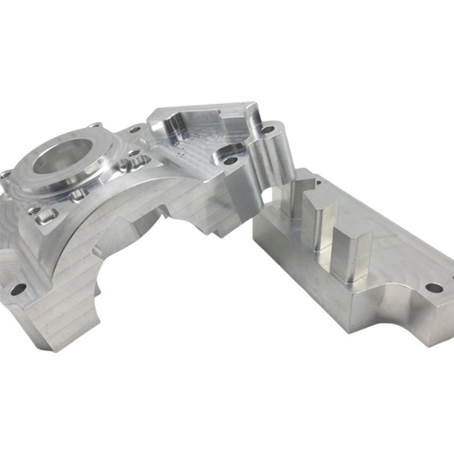
Aggressive cutting forces generate significant vibration and part deflection if the workpiece is not secured properly. Evaluating workholding solutions is a fundamental setup task. Standard precision vises handle most rectangular stock. However, complex geometries or secondary operations often require soft jaws machined to match the exact profile of the part. High-volume production runs justify the engineering of custom-machined fixtures, which utilize hydraulic or pneumatic clamps to ensure rapid, repeatable part loading.
Once the stock is secured, the operator establishes the Work Coordinate System (WCS). This process synchronizes the physical raw material inside the machine with the digital coordinate system in the CAM software. Modern machining centers utilize automated spindle probes to touch off the edges of the stock, setting exact X, Y, and Z zero points (typically G54 through G59). Perfect alignment prevents scrapped parts on the very first cut.
Matching cutting tools to the specific material and required surface finish dictates the quality of the final part. Machinists select from a massive inventory of endmills, drills, face mills, and chamfer mills. Cutting aluminum allows for polished, high-flute-clearance carbide tools. Machining stainless steel requires rigid, multi-flute endmills with advanced coatings like Titanium Aluminum Nitride (TiAlN) to withstand high temperatures.
Operators must set precise tool length offsets using a tool presetter or a table-mounted tool probe. If the machine does not know the exact length and diameter of the tool, it will cut too deep or crash into the table. Establishing a monitoring protocol for tool wear predictability is vital during longer production runs. Tools degrade over time, altering part dimensions. Operators execute a "dry run" or "air cutting" validation phase. Running the G-code with the Z-axis offset above the raw stock allows the operator to physically verify clearance planes, tool changes, and rapid movements before the cutter engages the material.
The physical machining process splits into two distinct phases: roughing and finishing. The strategy behind bulk material removal focuses on clearing stock as quickly as possible. Programmers utilize High-Efficiency Milling (HEM) toolpaths to maintain a constant radial engagement. This allows for deeper cuts and faster feed rates without overloading the tool. Roughing generates immense heat. Proper coolant application and optimized toolpaths minimize thermal distortion and prevent stress induction in the workpiece.
Roughing leaves a small envelope of material—typically 0.010 to 0.020 inches—for the finishing pass. Finishing parameters prioritize dimensional accuracy and surface finish over speed. Machinists increase spindle speeds and decrease feed rates, utilizing sharp, dedicated finishing tools. This pass removes the final layer of material with minimal cutting pressure. To eliminate tool deflection entirely, operators often program a "spring pass," which runs the exact same finishing toolpath a second time to shave off microscopic amounts of material left behind by tool bending.
Highly specialized components demand workflow shifts. Consider the requirements of 5-Axis Custom CNC Milling for Robotics Parts. Robotic components prioritize extreme lightweighting and feature complex joint geometries. Machining these intricate, thin-walled aluminum or titanium structures requires specialized workholding to prevent crushing the part. Feed rates must be reduced during finishing passes to prevent the thin walls from vibrating or deflecting away from the cutter.
Aerospace and medical applications present similar challenges. Machining deep pockets in structural aircraft components involves a constant trade-off between speed and precision. Pushing the machine too fast induces chatter, ruining the surface finish and potentially compromising the structural integrity of the part. Machinists adapt by using variable-pitch endmills and implementing strict in-process inspection routines to verify dimensions before removing the part from the fixture.
A part is rarely finished the moment it leaves the milling machine. Engineers must evaluate the functional and aesthetic trade-offs between leaving parts as-machined versus applying secondary finishes. As-machined parts show visible tool marks. While acceptable for internal mechanical components, external parts often require bead blasting to create a uniform matte finish.
Functional coatings like anodizing, passivation, or electroless nickel plating enhance corrosion resistance and surface hardness. However, these secondary finishes directly impact final tolerances. Type III hardcoat anodizing can add up to 0.002 inches of thickness to a surface. This dimensional growth must be accounted for during the initial CAD/CAM phase. Machinists will intentionally cut holes slightly oversized or leave external dimensions undersized to accommodate the plating thickness. Masking specific areas of the part prevents coating buildup on critical bearing surfaces or threaded holes.
Quality assurance validates the entire workflow. Metrology technicians use Coordinate Measuring Machines (CMM), optical comparators, and precision gauges to inspect the physical part. The First Article Inspection (FAI) report verifies every dimension on the machined component against the original 2D drawing and 3D CAD model. A CMM uses a highly sensitive ruby-tipped probe to map the geometry of the part, ensuring complex features like true position, cylindricity, and flatness meet the specified GD&T callouts.
Regulated industries demand strict compliance verification. Aerospace and medical sectors require documented material certifications to prove the exact chemical composition of the raw stock. Maintaining full traceability—from the initial material heat lot to the final inspection report—ensures compliance with rigorous quality management standards like AS9100 and ISO 9001.
Aggressive material removal generates significant friction. The resulting thermal expansion causes the workpiece to grow during machining. If a machinist finishes a part while it is hot, the dimensions will shrink as the metal cools, causing the part to fail inspection. Implementing high-pressure flood coolant or through-tool mist strategies mitigates this dimensional drift by stabilizing the temperature of the cutting zone.
Deep-cavity machining frequently introduces chatter—a self-exciting vibration that destroys surface finishes and shatters carbide tooling. Chatter occurs when the tool overhang is too long, reducing rigidity. Machinists resolve these issues by utilizing variable-flute endmills, which disrupt the harmonic frequencies that cause vibration. Adjusting spindle speeds and reducing the depth of cut also stabilize the cutting dynamics.
Selecting a manufacturing vendor requires looking beyond hourly machine rates. Assess a vendor's internal DFM feedback loop. Prioritize partners who proactively identify design flaws, suggest tolerance adjustments, and recommend standard tooling before cutting chips. A robust DFM review prevents costly revisions during production.
Evaluate a vendor's scalability. Transitioning from rapid prototyping to low-volume production requires substantial infrastructure. Ensure the partner possesses adequate machine capacity, utilizes integrated software ecosystems for CAD-to-CAM handoffs, and maintains strict quality control systems. A vendor relying solely on manual calipers cannot reliably support complex, high-tolerance production runs.
A successful custom CNC machining workflow relies heavily on front-loaded engineering, precise CAM programming, and rigorous setup protocols, rather than just the physical cutting of metal. Ignoring design for manufacturability or rushing the digital simulation phase guarantees wasted material and blown budgets. By standardizing CAD models, selecting the correct multi-axis strategy, and planning for secondary finishes early, engineers ensure their designs transition flawlessly to the shop floor.
Next Steps:
Audit your current CAD models to eliminate unnecessary tight tolerances and non-standard internal radii.
Define the critical mating surfaces and functional requirements for your parts using standard GD&T practices.
Compile your native 3D files, 2D drawings, and material requirements into a standardized technical package.
Submit your files to a qualified manufacturing partner for a comprehensive DFM review to receive an accurate, production-ready quote.
A: Lead times depend on part complexity, material availability, and production volume. Simple 3-axis parts often ship in three to five days. Complex multi-axis components requiring custom fixturing or secondary surface treatments take two to four weeks. Submitting standardized CAD files and finalizing tolerances early accelerates the quoting and programming phases.
A: A 3-axis mill moves the cutting tool along the X, Y, and Z linear axes. A 5-axis machine adds two rotational axes, allowing the tool to approach the workpiece from virtually any angle. This enables the machining of compound curves and allows five sides of a part to be cut in a single setup, drastically improving precision.
A: Standardized, non-native formats like STEP (.stp) and IGES (.igs) are universally accepted and preserve solid body geometry perfectly. Native files from platforms like SolidWorks, Fusion 360, or Inventor are also highly preferred, as they retain the parametric design history and allow CAM programmers to easily isolate specific features.
A: Reduce costs by applying tight tolerances only to critical mating surfaces. Standardize all internal corner radii to match common endmill sizes, and ensure the radii are slightly larger than the tool to prevent corner dwelling. Limit cavity depths to four times the tool diameter and avoid designing features that require custom-ground tooling.
A: G-code is the alphanumeric language commanding the machine's exact movements, speeds, and tool changes. Because different machine brands read code slightly differently, a post-processor translates the generic toolpaths generated by the CAM software into the specific syntax required by the target machine controller.
A: A roughing pass removes bulk material as quickly as possible using aggressive feed rates and deep cuts, leaving a small envelope of stock. A finishing pass uses higher spindle speeds, lower feed rates, and dedicated sharp tooling to remove the remaining material, achieving the final dimensional tolerances and required surface finish.


