English ![]()

No. 7, Tianyang 6th Road, Dongfang Community, Songgang Street, Bao'an District, Shenzhen, Guangdong, China(518100)
Views: 162 Author: Site Editor Publish Time: 2026-06-16 Origin: Site
Transitioning from product development to end-use manufacturing requires a critical choice in production technology. Making the wrong decision can derail your entire launch timeline. Whether you are developing lightweight chassis for humanoid robots or high-precision optical instruments, you need reliable methods to scale effectively. While additive manufacturing has advanced rapidly, deciding between it and subtractive manufacturing for actual production runs dictates unit economics, lead times, and part reliability. You must carefully weigh the upfront setup costs against long-term scalability. A single misstep here impacts profitability directly and delays market entry.
This guide provides a direct, evidence-based evaluation framework to help engineering and procurement teams. We will determine the exact crossover points where CNC machining services outperform 3D printing for production volumes. You will learn how to balance precision capabilities, material demands, and production speed. This article outlines the precise volume thresholds and performance limits governing both manufacturing methods today.
3D printing dominates low-volume, highly complex prototype geometries where traditional tooling or setup costs are prohibitive.
CNC machining is mandatory when isotropic material strength, tight tolerances, and superior surface finishes are non-negotiable for end-use parts, such as telescope bodies or robotic joint actuators.
The "cost crossover point" usually occurs between 100 and 500 units, depending on part complexity and material requirements.
Comparing the unit economics of additive and subtractive manufacturing reveals distinct financial curves. You must analyze the high initial setup cost of machining against the flat per-unit cost of 3D printing. Machining requires CAM programming, specialized cutting tools, and custom fixturing. These upfront engineering hours cost money before the first chip flies. 3D printing avoids this hurdle completely. You upload a CAD file directly to the slicing software. The printer then begins creating the part without custom physical tooling.
However, you must define the typical volume break-even point. This cost crossover point usually sits between 100 and 500 units. 3D printing scales poorly for large production batches. Machine cycles remain incredibly slow. A print head tracing laser paths takes hours to complete a single layer. Conversely, subtractive unit costs drop drastically at scale. Once the initial setup finishes, a spinning carbide end mill removes material in mere seconds. Machine operators run hundreds of identical parts efficiently.
| Production Volume | 3D Printing Cost Per Unit | CNC Machining Cost Per Unit | Recommended Process |
|---|---|---|---|
| 10 Units | $45.00 | $150.00 (Setup Heavy) | 3D Printing |
| 100 Units | $42.00 | $48.00 | Crossover Zone |
| 500 Units | $40.00 | $18.00 | CNC Machining |
| 1,000+ Units | $38.00 | $12.00 (Scale Economics) | CNC Machining |
You must also contrast the speed to market. Additive manufacturing deploys rapidly. Engineers print functional prototypes overnight. Yet, machining boasts much faster per-part cycle times once actual production begins. You can machine twenty aluminum brackets or motor housings in the time it takes to print one.
Tip: Always calculate your total landed cost for a 500-part run. You must factor in the manual labor required for post-processing 3D-printed parts. Support removal and surface sanding often eat directly into your initial tooling cost savings.
Engineers must understand the profound structural risks of layer-by-layer fabrication. 3D printed components suffer from anisotropic material properties. They exhibit inherent Z-axis weakness. Parts often shear or delaminate along the layer lines under heavy mechanical stress. Machined parts provide solid billet integrity. They possess isotropic properties. Material strength remains completely uniform in every direction. You can trust billet metals under extreme load conditions.
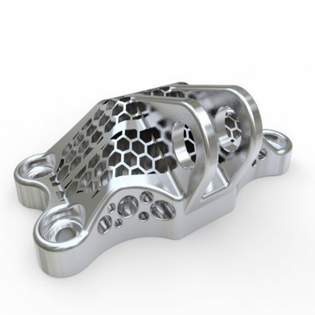
Consider the intense demands of the booming humanoid robot industry. Components like robotic joint actuators, structural chassis, and motor housings require extreme durability and lightweight properties. 3D printed polymers or porous printed metals often fail under these dynamic, high-torque loads. Here, CNC machined aluminum (like AL 7075) and titanium unlock a massive catalog of certified production-grade metals that ensure long-term mechanical reliability.
High-compliance applications demand verifiable material traceability. Heavily regulated sectors require strict documentation. Consider the growing demand for custom 5 Axis CNC machining services for new energy. Electric vehicle battery plates and hydrogen fuel cell components operate in extreme environments. They must carry heavy certifications to prevent catastrophic field failures, making traditional billet machining the safer choice over powder-based 3D printing.
High-compliance energy and robotics components require the verifiable structural integrity and precision delivered by advanced machining techniques.
Dimensional accuracy dictates the success of final mating parts. You must contrast standard printing tolerances against high-precision cutting capabilities. Typical industrial 3D printers hold tolerances between ±0.1 mm and ±0.3 mm. Precision cutting centers easily achieve tolerances of ±0.01 mm to ±0.05 mm on a daily basis.
You rely on this accuracy for tight bearing fits and absolute optical alignment. For instance, in a recent high-end manufacturing project for a Belarusian client's telescope accessories, we utilized advanced CNC machining to manufacture a complete suite of precision optical parts. The project required perfectly matched components, including the Gasket, Sleeve, Frame, Catcher, Coil, Body, Plank, Fixer, Flange, Rack, Carriage, and Holder. These critical optical instruments required immaculate surface finishes (Ra < 0.4 μm) and perfect concentricity to prevent light leakage.
Additive processes suffer from an inherent stair-stepping effect, leaving visible ridges that require unpredictable manual sanding. A mill or lathe produces smooth, uniform finishes immediately. The machine leaves the telescope sleeve or camera body ready for matte black anodizing without manual intervention. Modern machine capabilities handle complex geometries efficiently. We detail how 5-Axis CNC machining bridges the gap, allowing for complex undercut milling on a telescope carriage or robot frame in a single setup.
| Parameter | Industrial 3D Printing | Advanced CNC Machining |
|---|---|---|
| Standard Tolerances | ±0.1 mm to ±0.3 mm | ±0.01 mm to ±0.05 mm |
| Surface Finish (As Made) | Ra 3.2 to Ra 12.5 (Visible layers) | Ra 0.4 to Ra 1.6 (Smooth) |
| Internal Geometries | Excellent (Can print enclosed voids) | Limited (Requires line-of-sight) |
| Post-Processing | High (Support removal, sanding) | Low (Deburring, direct plating) |
Moving a product from prototype to mass production introduces significant friction. You face a major Design for Manufacturing (DFM) shift. You cannot simply take a file optimized for printing and run it on a mill. Engineers must eliminate features impossible to cut.
Consider these critical DFM steps when preparing for mass production:
Remove internal voids: Cutting tools require direct access lines. You must split enclosed cavities into two separate machineable halves.
Standardize corner radii: Square inside corners are impossible to mill. You must design internal fillets matching standard cutting tool diameters.
Optimize wall thickness: Tall, paper-thin walls vibrate violently during cutting. You must thicken them to withstand heavy spindle forces.
Reduce deep pockets: End mills deflect when reaching too deeply. You should limit pocket depth to four times the tool diameter.
A smart prototyping strategy leverages the strengths of both technologies. You use additive systems for rapid form and fit testing. You print three iterations of a telescope holder in one weekend to check ergonomics. Then, you move to subtractive processes for functional testing. Consider the standard workflow for creating automotive prototyping parts. Engineers print initial plastic intake manifolds to test engine bay clearances, then machine the final prototype from solid aluminum for intense under-the-hood thermal testing.
Innovative manufacturers no longer view these processes as mutually exclusive. They embrace a hybrid strategy. You can combine additive and subtractive methods to maximize efficiency and precision.
Leveraging both processes builds resilient supply chains and mitigates risk. Consider the following hybrid advantages:
Supply Chain Security: You can print urgent stop-gap replacement parts overnight while waiting for the main high-volume production runs to finish.
Custom Tooling Production: You can quickly print custom soft jaws, nesting fixtures, and assembly jigs using durable polymers to hold complex shapes like a telescope flange or a robot plank during the final CNC milling process.
Material Optimization: Printing near-net shapes drastically reduces the volume of metal chips generated during the final finishing pass.
Your production success depends entirely on matching the right technology to your project parameters. Choose 3D printing for low-volume runs under 100 units. It excels at highly customized, complex geometries where extreme material strength remains secondary. Conversely, select precision machining for medium-to-high volumes. You need it for tight tolerances, superior surface finishes, and high-stress mechanical environments found in robotics, aerospace, and high-end optics.
Do not rely on guesswork to determine your cost crossover point. We recommend requesting simultaneous manufacturing quotes for both processes early in your design phase. Partner with a versatile manufacturer like Shenzhen Zhongyi Precision Technology who provides honest DFM feedback. Calculate your total landed costs, run your prototype tests, and commit confidently to the method yielding the best long-term unit economics.
A: The cost crossover point typically occurs between 100 and 500 units. 3D printing offers low initial setup costs but high flat per-unit costs. Machining requires expensive upfront programming and fixturing. However, its fast cycle times cause the per-unit cost to drop drastically as production volume increases.
A: Sometimes, but printed metals face challenges with density and porosity. They exhibit lower isotropic strength compared to solid billet metals used in robot joints. Furthermore, 3D printed metal parts almost always require secondary subtractive post-processing to achieve the smooth surface finishes and tight tolerances needed for mechanical mating surfaces and optical sleeves.
A: Multi-axis machines eliminate traditional subtractive limitations. A 5-axis mill reaches multiple sides of a part in a single setup. It successfully achieves the highly complex, organic geometries traditionally thought only possible with additive printing, while delivering the structural integrity of production-grade solid metal.


