
English ![]()

No. 7, Tianyang 6th Road, Dongfang Community, Songgang Street, Bao'an District, Shenzhen, Guangdong, China(518100)


| Quantity: | |
|---|---|
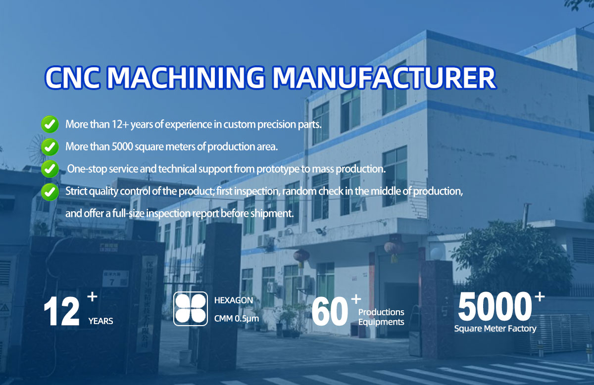
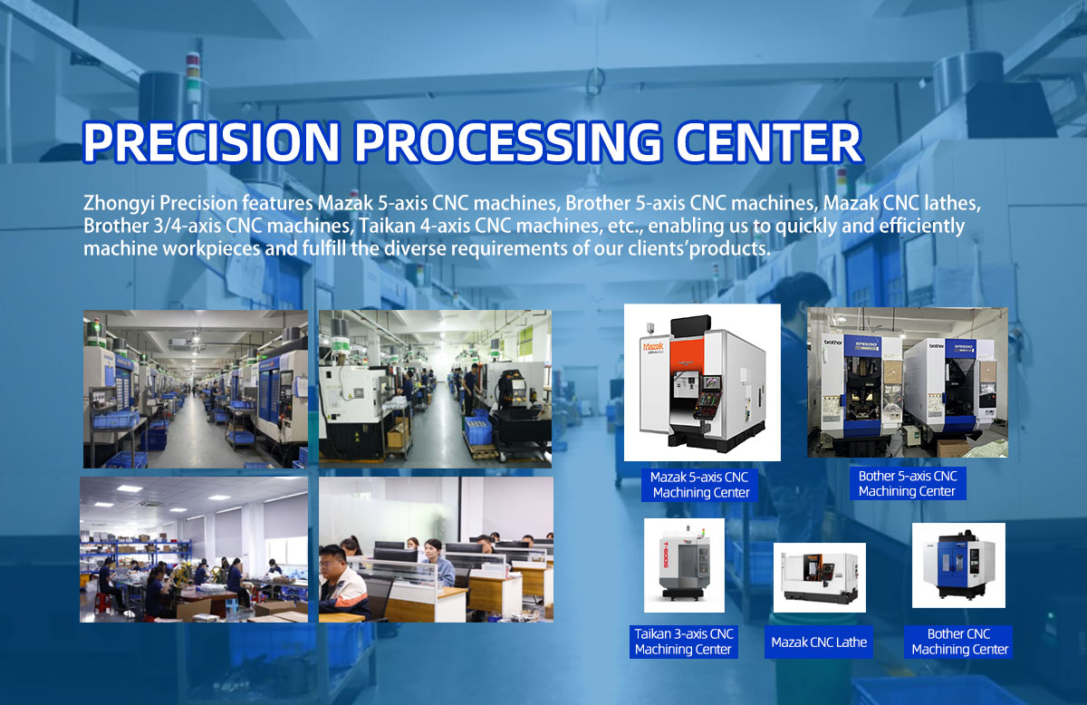
Our CNC milling services produce aluminum precision components engineered for optical system assembly, serving industrial clients across photonics, imaging, laser systems, and scientific instrumentation sectors. We operate multi-axis CNC machining centers configured for tight-tolerance aluminum fabrication, with process controls aligned to optical assembly requirements. All production runs follow documented work instructions, with material traceability maintained for each batch.
Our facility maintains ISO 9001:2015 certification, with all aluminum materials sourced from approved mills with material test reports available upon request. We support both prototype development and volume production, with dedicated engineering support for design for manufacturability reviews prior to production kickoff. Typical components include lens mounting hardware, optical bench structures, and sensor alignment fixtures that require consistent dimensional stability across operating temperatures.
Parameter | Specification |
|---|---|
Primary Process | 3-axis, 4-axis, and 5-axis CNC milling |
Secondary Operations | CNC turning, drilling, tapping, deburring, surface treatment |
Aluminum Grades | 6061-T6, 7075-T6, 5052, 2024, 6063 |
Additional Materials | 304/316 stainless steel, brass, copper, titanium, PEEK, acrylic, POM |
General Tolerance | ±0.005mm |
Critical Feature Tolerance | ±0.001mm |
Optical Alignment Tolerance | ±0.01mm for lens seat concentricity |
Surface Roughness Range | Ra0.2 - Ra3.2 |
Optical Mount Surface Finish | Ra0.4 standard, Ra0.2 optional |
Drawing Formats Accepted | STEP, STP, IGES, DWG, DXF, PDF |
Surface Treatment Options | Clear anodized, color anodized, sandblast anodized, chemical conversion coating, polishing, brushing, passivation, laser engraving |
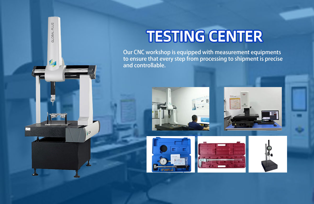
Inspection Equipment | CMM, optical comparator, digital caliper, height gauge, micrometer, surface roughness tester, hardness tester, salt spray chamber |
Certifications | ISO 9001:2015, RoHS compliant |
Prototype Lead Time | 3-5 working days |
Production Lead Time | 15-25 working days, depending on volume and complexity |
Minimum Order Quantity | 1 piece for prototypes, 50 pieces for production runs |
 |  |  |
We machine lens barrels, lens cells, and adjustable mounts with concentric seat diameters to maintain optical centration. Threaded interfaces for focus adjustment are cut with consistent pitch diameters, while retaining ring grooves are machined to specified depths to prevent lens stress during assembly. Black anodizing is available for internal surfaces to reduce stray light reflections.
Spectrometer frames, interferometer bases, and breadboard components are machined from stress-relieved aluminum to maintain flatness across temperature cycles. We produce T-slot surfaces and mounting hole patterns with consistent position tolerances to ensure component interchangeability during system assembly. Vibration-damping features can be incorporated into base structures per print specifications.
Laser diode mounts, beam steering brackets, and aperture holders include thermal management channels for heat dissipation. Fiber alignment V-grooves are machined to micron-level position accuracy to support low-loss coupling. Mirror mounts include fine adjustment thread interfaces with consistent torque characteristics for precision alignment.
Infrared camera housings, machine vision bodies, and detector assemblies include gasket grooves for environmental sealing, with mounting bosses positioned to maintain sensor alignment. Internal light baffling features are machined in single setups to eliminate assembly stack-up errors that could cause stray light issues.
All aluminum stock is stress-relieved prior to finish machining, with roughing and finishing operations separated to minimize part movement. Critical features are machined after temperature stabilization of both the workpiece and machine structure. We document fixture locations and tool offsets for production runs to ensure consistency across batches.
Cutting parameters are optimized for aluminum to prevent built-up edge and surface smearing that could affect optical performance. All parts go through controlled deburring processes, with edges broken to print specifications. Surface roughness measurements are taken on critical mounting surfaces using contact profilometers.
First article inspection reports are provided for all new production runs, with dimensional data recorded for all critical features. Material certificates, plating certifications, and inspection reports can be included with shipments per customer requirements. Lot numbers are maintained throughout production to support traceability.
We maintain ±0.01mm concentricity for lens mounting diameters, with total indicated runout verified on CMM for critical applications. Tighter tolerances are available for specialized applications following engineering review.
Black anodizing per MIL-A-8625 Type II Class 2 provides consistent light absorption for internal surfaces. We also offer matte bead blasting prior to anodizing to produce uniform, non-reflective surfaces with Ra1.6 - Ra3.2 roughness.
Yes, we provide dimensional inspection reports for first articles, including CMM data for all critical features. Material certifications and surface treatment certificates are available upon request for production orders.
We maintain 0.5mm minimum wall thickness for most aluminum optical components, with 0.3mm walls possible on features with sufficient support. Engineering review is recommended for walls thinner than 0.8mm to ensure structural integrity.


