
English ![]()

No. 7, Tianyang 6th Road, Dongfang Community, Songgang Street, Bao'an District, Shenzhen, Guangdong, China(518100)
Views: 0 Author: Site Editor Publish Time: 2026-10-29 Origin: Site
Machining burrs cause immediate operational headaches on the shop floor. These microscopic material remnants cling to tool exit points, creating severe assembly interference. They accelerate component wear and compromise safety in precision applications like aerospace and medical device manufacturing. Managing these defects requires constant vigilance from production teams.
A fundamental tension exists between pushing aggressive cycle times and maintaining pristine edge quality. Subtractive manufacturing inherently causes plastic deformation and material shifting. When left unmanaged, these edge defects inflate secondary processing costs and jeopardize strict quality control standards. Manufacturers must address this issue directly to maintain production efficiency.
Mitigating these defects requires a comprehensive, dual-pronged approach. First, machinists must diagnose the mechanical root causes directly at the spindle. Second, facilities need an engineered CNC machining burr removal strategy tailored to the specific part geometry, material, and volume. Proactive planning eliminates downstream bottlenecks and keeps production moving.
Burr formation is primarily driven by plastic deformation at the tool exit, exacerbated by improper uncut chip thickness, dull tooling, and suboptimal feed rates.
Material ductility plays a critical role; softer, gummy metals like copper and certain aluminum alloys are highly susceptible to rollover, material adhesion, and built-up edge (BUE).
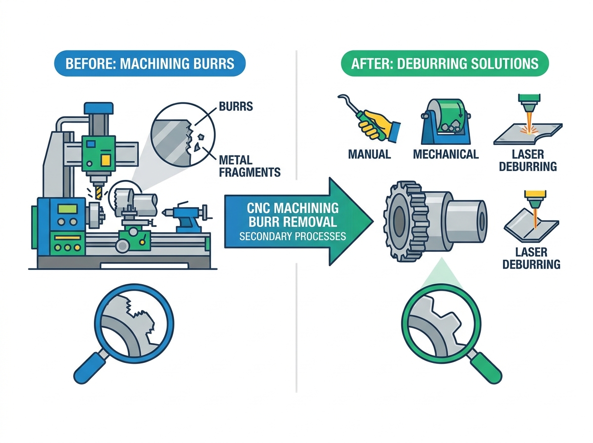
Selecting a CNC machining burr removal method requires balancing tolerance constraints against production scalability—ranging from manual finishing to automated electrochemical processes.
Proactive toolpath optimization, varying cutting speeds, and rigid workholding can significantly reduce the severity of burrs, minimizing the reliance on secondary deburring operations.
Understanding the physical process of burr creation is the first step toward prevention. During the cutting process, the tool shears material away along a specific shear plane. However, the final layer of material often distorts instead of cutting cleanly. It shifts away from the cutting tool because the material yields to plastic deformation before the cutting edge can sever it completely. This plastic flow leaves unwanted material attached to the workpiece.
Engineers categorize these defects based on how the material flows during the cut. A Poisson burr occurs due to lateral material flow under heavy compression. As the cutting tool presses down, the material bulges outward at the edges, creating a raised lip. Conversely, a rollover burr forms as the tool exits the workpiece. The tool bends the remaining thin layer of material forward, creating a distinct, folded flap along the exit edge. Rollover burrs are typically the largest and most problematic defects encountered in milling operations.
Other variations include tear burrs and cut-off burrs. Tear burrs happen through sideward tearing during punching or heavy milling operations where the material rips rather than cuts cleanly. Cut-off burrs are remnants left behind when a part separates from the main stock before the parting tool finishes the cut. Gravity or machine vibration causes the part to snap off early, leaving a jagged spike on the center of the turned part.
Certain geometries represent high-risk zones for edge defects. Identifying these zones helps programmers adjust toolpaths accordingly. Common problem areas include:
Drilled holes breaking through angled surfaces.
Intersecting internal cross-holes in hydraulic manifolds.
Sharp external edges on milled profiles.
Tool exit points during face milling operations.
Thread runouts on turned shafts.
Tool wear directly influences edge quality. Dull cutting edges increase cutting pressure dramatically. Instead of slicing through the metal, a dull tool pushes it. This forces the material to deform plastically. Regular tool inspection and strict replacement schedules prevent this unnecessary deformation. Machinists must monitor spindle load meters to catch dulling tools before they destroy edge quality.
Improper tool geometry also contributes to material pushing. Rake angles and helix angles must match the specific material being cut. Insufficient clearance behind the cutting edge rubs against the workpiece, generating heat and pushing material outward. Incorrect edge preparation fails to shear the chip properly. Using a tool designed for steel on a block of aluminum guarantees poor edge quality.
Chip evacuation failures compound the problem. Poor chip clearance leads to recutting chips. This generates excessive heat and causes material adhesion. The workpiece material welds to the cutting tool, creating a built-up edge (BUE). A tool with BUE effectively changes its own cutting geometry. It creates irregular edge defects, increases friction, and significantly exacerbates burr size.
Feed rates and cutting speeds share a direct relationship with burr size. Improper speed-to-feed ratios alter the cutting dynamics. Varying conditions of uncut chip thickness lead to larger exit burrs. Pushing a tool too fast through the exit point almost guarantees a massive rollover defect. The tool pushes the thick chip forward instead of shearing it.
Excessive cutting pressure induces severe thermal and mechanical stress. Aggressive depths of cut overwhelm the material's shear strength. The workpiece material yields and flows outward to escape the pressure. Optimizing the depth of cut keeps forces within acceptable limits and allows the tool to shear the material efficiently.
Coolant and lubrication deficiencies worsen the situation. Inadequate thermal management allows heat to build up rapidly in the cutting zone. High temperatures increase material ductility. Softer material stretches and bends instead of breaking cleanly. Proper coolant application keeps the material brittle enough to shear while flushing chips away from the cut.
Material ductility dictates how easily a metal shears. Materials with high ductility naturally resist clean cutting. They tend to tear and roll over. Machining these gummy metals requires specialized sharp tooling with high positive rake angles. Brittle materials, on the other hand, tend to chip rather than form long, stringy burrs.
Workpiece rigidity plays a massive role in edge quality. Micro-vibrations disrupt the cutting process. Inadequate clamping allows the workpiece to flex away from the tool. When the material moves, the tool cannot finish the cut cleanly. This deflection leaves a prominent burr behind. Rigid setups using proper vise jaws and fixture plates eliminate this movement.
| Material Type | Ductility Level | Primary Burr Type | Machining Risk Factor |
|---|---|---|---|
| Copper / Brass (Low Lead) | Very High | Rollover / Tear | Extreme risk of material adhesion and BUE. |
| Low-Carbon Steel (1018) | High | Rollover | Tends to push and tear without sharp tooling. |
| Aluminum (6061-T6) | Medium | Poisson / Rollover | Moderate risk; highly dependent on tool sharpness. |
| Cast Iron | Low (Brittle) | Breakout / Chipping | Low burr risk, but high risk of edge breakout. |
| Titanium (Ti-6Al-4V) | Medium | Poisson | High heat generation causes localized plastic flow. |
Toolpath optimization serves as the first line of defense on the shop floor. Programmers use roll-in and roll-out milling techniques to manage tool engagement smoothly. Climb milling directs cutting forces into the bulk of the material rather than toward the unsupported edge. This strategy minimizes tool exit burrs effectively because the chip thickness decreases to zero as the tool exits the cut.
Parameter tuning at specific locations yields excellent results. Reducing the feed rate specifically at the tool exit point decreases the uncut chip thickness. A thinner chip requires less force to shear. This targeted reduction significantly reduces rollover burrs without impacting overall cycle times heavily. Machinists can program feed rate drops just millimeters before the tool breaks through the material.
In-cycle chamfering eliminates manual work entirely. Programmers integrate chamfer mills, spot drills, or custom form tools into the primary machining cycle. These tools break sharp edges before the part leaves the machine. Using lollipop cutters allows machines to deburr complex undercuts and intersecting cross-holes from the inside out. This proactive approach prevents the need for any downstream removal operations and guarantees consistent edge breaks across every part.
Operators frequently rely on traditional hand tools, deburring blades, and abrasive nylon brushes. Facilities also integrate mechanical chamfering tools directly into the machine tool carousel. Alternatively, workers utilize offline workstations equipped with rotary tools and abrasive wheels. These methods provide tactile feedback during the finishing process, allowing operators to feel the edge quality.
Implementing manual and mechanical deburring for CNC parts makes sense for low-to-medium volume production. Complex geometries often require human tactile inspection to ensure quality. In-machine mechanical deburring saves overall cycle time by eliminating secondary routing. Abrasive nylon brushes run directly in the CNC spindle can sweep across flat faces, removing micro-burrs without altering part dimensions.
However, these methods carry distinct limitations. Human error leads to inconsistency in edge breaks across a batch. Manual filing introduces localized scratches that may fail cosmetic inspections. Furthermore, relying on hand finishing drives up labor costs significantly during high-volume production runs and creates massive bottlenecks before final inspection.
This process utilizes focused thermal energy to vaporize micro-burrs. The laser travels along the edges of profiled sheet metal and thin-walled components. It melts and evaporates the excess material instantly. The non-contact nature of the tool prevents physical stress on the part, eliminating the need for heavy clamping fixtures.
Using laser deburring for sheet metal components excels in specific scenarios. It proves highly effective for intricate, flat profiles cut by waterjets or punch presses. Applying mechanical force to these delicate parts would cause distortion or edge rolling. Lasers preserve the structural integrity of thin materials while providing a clean, burr-free edge.
The limitations involve heat management. The process creates heat-affected zones (HAZ) along the cut edge. This can cause micro-structural changes or unintended tempering, making the edge brittle. Additionally, laser systems require a high initial capital expenditure compared to mechanical tools, requiring high production volumes to justify the ROI.
Mass finishing techniques handle large batches of components simultaneously. Common methods include vibratory finishing, tumble deburring, and centrifugal barrel finishing. Parts agitate inside a polyurethane-lined tub filled with abrasive media (like ceramic triangles or plastic cones) and liquid compounds. The friction gently wears away sharp edges over a set cycle time.
Facilities rely on secondary deburring for aluminum die cast parts when volume demands it. It works perfectly for robust aluminum castings straight out of the mold. The process provides uniform surface finishing, flash removal, and edge radiusing all at once. It requires minimal operator intervention; workers simply load the hopper and walk away.
Risks exist when processing precision components. Aggressive tumbling alters critical dimensional tolerances on machined faces. Heavy media can damage delicate external threads or bend thin protrusions. Furthermore, small abrasive stones frequently lodge inside blind holes, requiring manual removal later with picks or compressed air.
The Thermal Energy Method (TEM) uses combustible gas mixtures. The machine seals the part in a heavy-duty chamber and ignites a methane-oxygen mixture. The intense, brief heat oxidizes and vaporizes burrs instantly because their high surface-area-to-mass ratio causes them to burn up before the main body of the part absorbs the heat. This works perfectly for internal cross-holes and complex hydraulic manifolds.
Electrochemical Deburring (ECD) relies on anodic dissolution. A custom-shaped cathode targets specific edges. An electrolyte solution flows between the tool and the part. The electrical current dissolves the burr precisely. This provides highly precise, localized removal for critical aerospace or medical components without inducing any mechanical or thermal stress.
Abrasive Flow Machining (AFM) pushes a specialized abrasive putty through internal cavities. Hydraulic cylinders force the polymer medium back and forth through the part. The putty acts as a flexible file, conforming to the internal geometry. It removes internal burrs and polishes complex passageways simultaneously, making it ideal for fuel injectors and extrusion dies.
Line-of-sight limitations dictate equipment selection. External features allow for mechanical brushes, manual filing, and robotic grinding. Internal cross-holes block physical access entirely. These hidden features require AFM, ECD, or TEM to guarantee complete removal without cutting the part open to reach the defect.
Dimensional integrity remains the top priority. Engineers must select methods that will not alter tight-tolerance bores or sealing surfaces. For example, aggressive vibratory finishing ruins precision bearing journals by rounding the edges and altering the diameter. ECD protects adjacent surfaces while targeting only the specific edge that requires finishing.
Cost-per-part analysis drives process adoption. Manual deburring carries a high variable labor cost but requires zero capital investment, making it suitable for prototyping. Automated ECD or TEM systems demand high fixed costs upfront for the machinery and custom tooling. However, their low variable cost per part makes them highly profitable over long production runs.
Throughput requirements dictate workflow planning. Secondary operations impact overall lead times. High-volume manufacturing cannot tolerate slow manual finishing. Automated batch processes manage bottlenecks effectively and keep parts moving toward assembly without waiting for hand-finishing stations to catch up.
Different methods impact the final surface finish differently. Tumbling improves overall surface roughness (Ra), adding secondary value to the part by polishing it. Conversely, manual filing may introduce localized scratches that require further polishing. The chosen method must align with final cosmetic requirements dictated by the customer.
Cleanliness and contamination present distinct challenges. Abrasive flow or chemical methods leave residue behind. Medical and semiconductor applications demand pristine surfaces. Post-deburring washing becomes a mandatory, added step when using these advanced methods, requiring ultrasonic cleaning tanks and strict drying protocols.
| Deburring Method | Ideal Production Volume | Best Application Geometry | Primary Risk Factor |
|---|---|---|---|
| Manual / Mechanical | Low to Medium | External edges, simple profiles | Inconsistent edge breaks, high labor cost |
| Laser Vaporization | Medium to High | Thin-walled sheet metal, flat profiles | Heat-affected zones (HAZ), tempering |
| Vibratory Tumbling | High (Batch) | Robust castings, external radiusing | Media lodging in blind holes, thread damage |
| Electrochemical (ECD) | Medium to High | Precision aerospace/medical, localized edges | High initial tooling cost, electrolyte disposal |
| Thermal Energy (TEM) | High (Batch) | Internal cross-holes, complex manifolds | Surface oxidation requiring post-cleaning |
| Abrasive Flow (AFM) | Medium | Internal passageways, extrusion dies | Media contamination, slow cycle times |
Uncontrolled processes easily remove base material alongside the burr. This pushes the part out of specified tolerance limits. A heavy hand with an abrasive wheel ruins a tight-tolerance diameter in seconds. Aggressive tumbling rounds off corners that need to remain sharp for mating components.
Mitigation requires strict engineering controls. Implement explicit edge-break callouts on engineering drawings. Use specific language like "Break edges 0.1-0.2mm" rather than the vague "Remove all burrs." Utilize in-process probing on the CNC machine to verify critical dimensions before and after the finishing operation.
Introducing excessive heat damages part integrity. Laser systems or aggressive mechanical grinding generate intense localized heat. This leads to warping in thin components. It also causes changes in material hardness, ruining previous heat-treatment processes and causing premature part failure in the field.
Careful calibration prevents thermal damage. Operators must calibrate laser wattage and pulse duration specifically for the sheet metal thickness. When using mechanical abrasive brushes or grinding wheels, ensure adequate coolant flow to dissipate heat immediately before it transfers into the bulk of the part.
Mission-critical environments tolerate zero defects. Undetected micro-burrs can detach during operation. A loose metal flake inside a hydraulic manifold causes catastrophic valve failure. Aerospace actuators seize if internal edges flake off under heavy vibration during flight.
Establish rigorous inspection protocols to ensure compliance. Use borescopes to inspect internal cross-holes visually. Employ optical comparators to measure edge breaks accurately against the print specifications. Standardized validation frameworks ensure complete removal in highly regulated industries, providing traceability for every batch.
Edge defects remain an inevitable byproduct of subtractive manufacturing. However, their operational impact can be entirely neutralized. Success requires a combination of optimized machining parameters at the spindle and engineered removal processes downstream. Ignoring the problem only shifts costs to assembly and quality control, resulting in rejected parts and delayed shipments.
The logic for shortlisting a strategy hinges on three factors: part geometry, material ductility, and production volume. Manual methods suit low-volume, simple parts. Automated methods offer the best return on investment for high-volume, tight-tolerance components. Properly executed edge management protects both part function and profit margins.
Take the following actions to improve your edge quality management:
Audit your current scrap rates and assembly failures directly related to edge defects.
Implement in-cycle chamfering toolpaths for all high-risk tool exit points to reduce manual labor.
Update engineering drawings with strict, measurable edge-break callouts to eliminate operator guesswork.
Consult a precision machining partner to integrate automated finishing into your next high-volume production run.
A: A Poisson burr forms when material bulges laterally outward due to heavy compression from the cutting tool. A rollover burr forms when the tool exits the cut, bending and pushing the remaining thin layer of material forward into a distinct flap.
A: Dull tools increase cutting pressure, forcing material to deform rather than shear cleanly. Material adhesion creates a built-up edge (BUE) on the tool, which alters the cutting geometry, increases friction, and leaves irregular, oversized remnants on the machined part.
A: Use extremely sharp tooling with high positive rake angles to shear the gummy material effectively. Apply generous coolant to manage heat, and utilize climb milling to direct cutting forces into the solid bulk of the workpiece rather than the unsupported edge.
A: Yes. Programmers use chamfer mills, custom form tools, and specialized abrasive nylon brushes loaded directly into the tool carousel. This breaks sharp edges during the primary cycle, eliminating the need for offline manual finishing and ensuring consistency.
A: Vibratory finishing and tumble deburring offer the best results for high-volume castings. These mass finishing techniques remove flash, radius edges, and improve overall surface finish simultaneously with minimal operator intervention, making them highly cost-effective for large batches.
A: Internal cross-holes require methods that do not rely on line-of-sight. The Thermal Energy Method (TEM) vaporizes internal defects using combustible gas. Abrasive Flow Machining (AFM) pushes abrasive putty through the holes to file edges internally. Electrochemical Deburring (ECD) dissolves them using localized current.
A: It can. If the wattage and pulse duration are not calibrated correctly, the heat creates a heat-affected zone (HAZ). This localized heat can warp thin material or alter the micro-structure, changing the local hardness and potentially ruining previous heat treatments.


