English ![]()

No. 7, Tianyang 6th Road, Dongfang Community, Songgang Street, Bao'an District, Shenzhen, Guangdong, China(518100)




| Quantity: | |
|---|---|
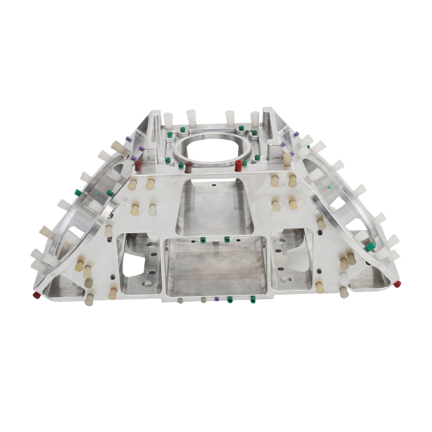
Custom-machined for compact humanoid robot joints and actuator assemblies, this precision joint end cap is produced directly from customer drawings or 3D CAD data. Complex profiles, mounting holes, locating features and precision interfaces can be completed through multi-axis machining while maintaining the dimensional relationships required for assembly.
Zhongyi Precision supports custom robot components from prototype verification to repeat production, with 5-axis CNC machining, dimensional inspection and manufacturing feedback based on your drawing requirements.
A humanoid robot joint end cap is more than an external cover. Depending on the actuator design, it may form part of the positioning, mounting, protection or structural interface of the joint assembly.
Features such as circular mounting patterns, internal steps, locating surfaces, threaded holes and precision bores may need to align with other components inside the joint. When several of these features are located on different faces or at different angles, machining them through repeated setups can introduce accumulated positioning error.
5-axis CNC machining provides greater access to these features while reducing unnecessary re-clamping of the workpiece.
For custom joint end caps, our manufacturing focus is therefore not only the tolerance of an individual dimension, but also the relationship between mating surfaces, hole patterns, bores and assembly datums defined on the customer's drawing.
Modern humanoid robot joints are designed around limited installation space. A single end cap may contain an outer contour, internal cavity, bolt-circle pattern, locating holes, threaded interfaces and several machined surfaces.
These features must be produced without interfering with adjacent motors, reducers, bearings, wiring or structural components.
A 5-axis machining strategy allows the cutter to approach the part from different orientations and helps consolidate operations that would otherwise require several fixtures.
A bore may meet its diameter tolerance while still causing assembly problems if its position relative to the mounting face is incorrect.
The same applies to bolt circles, locating holes, concentric features and opposing surfaces.
For this reason, robot joint components often require attention to both dimensional tolerances and geometric relationships. We review drawing datums and critical characteristics before determining the machining and inspection sequence.
Humanoid robot designers frequently remove unnecessary material to reduce joint mass and inertia.
The resulting pockets, ribs and thinner sections can make a component more sensitive to machining forces and material movement.
Machining sequence, workholding and cutting strategy therefore need to be considered together rather than treating every surface as an independent operation.
Producing one acceptable prototype is different from maintaining the same critical dimensions over repeated batches.
When a robotics program progresses from engineering samples to pilot production, fixture repeatability, tool control, inspection points and process consistency become increasingly important.
Our manufacturing workflow can support this transition without changing the fundamental drawing-defined acceptance criteria.
Production begins with the customer's technical information rather than a standard catalog design.
We review the 2D drawing and 3D model to identify:
Primary and secondary datums
Critical mounting surfaces
Precision bores
Hole patterns
Thread specifications
Thin-wall areas
Difficult tool-access regions
Geometric tolerance requirements
Surface finish specifications
Inspection requirements
This review allows the machining process to be planned around the actual function of the component.
The machining sequence is determined according to the geometry and critical datum structure of the end cap.
Where practical, important related features are machined from a common setup to reduce errors caused by repeated repositioning.
Stable locating surfaces are established early in the process so later machining operations can reference controlled datums.
5-axis equipment is used where the geometry requires access to several faces, angled features or complex profiles.
Typical operations may include:
Face milling
Circular interpolation
Precision boring
Pocket machining
Contour milling
Drilling
Tapping
Chamfering
Multi-angle feature machining
The process route is selected according to the component rather than forcing every part into the same machining method.
Bearing-related interfaces, locating surfaces, mating faces and other drawing-defined critical characteristics can receive dedicated finishing operations after rough machining.
Machining allowance, tool selection and measurement stages are adjusted according to tolerance requirements.
Small burrs around threaded holes, intersections, edges and internal features can interfere with robotic assembly.
Parts are therefore checked after machining and prepared for the specified finishing process or final inspection.
Depending on your CAD model and assembly design, we can machine features such as:
Feature | Typical Purpose |
|---|---|
Central bores | Shaft, bearing or actuator interface |
Circular bolt patterns | Connection to adjacent joint components |
Locating holes | Repeatable assembly positioning |
Threaded holes | Fastener installation |
Precision shoulders | Axial positioning of mating components |
Internal pockets | Weight reduction or component clearance |
Curved external profiles | Packaging and motion clearance |
Angled holes | Fastening, routing or assembly access |
Grooves | Sealing or retaining features |
Mating faces | Connection to actuator or structural assemblies |
Cable openings | Internal routing where required by the design |
Recessed areas | Component clearance and weight reduction |
All dimensions and features are manufactured according to the customer's drawing rather than fixed catalog specifications.
Material selection should be based on structural load, component weight, operating environment, surface requirements and the design of the complete actuator assembly.
Aluminum alloys are frequently selected for robotic structural components because they combine relatively low weight with good machinability.
They are particularly suitable for joint components with pockets, ribs and complex machined geometry where controlling overall mass is important.
Natural anodizing or other specified finishing processes can be applied to suitable aluminum components according to drawing requirements.
Stainless steel may be selected when the component requires different strength, wear or corrosion characteristics.
Because its machining behavior differs from aluminum, machining parameters and tool strategies are selected accordingly.
Titanium can be considered for applications where the design places greater emphasis on strength-to-weight performance.
Its machining requirements, cycle time and tooling considerations differ significantly from aluminum and should therefore be evaluated during quotation.
Other engineering materials can also be reviewed according to the customer's technical specification.
Quality control begins before the final inspection.
Our existing production system uses three main inspection stages so dimensional issues can be identified before a complete batch has been manufactured.
The initial machined part is checked against drawing requirements before the production process continues.
Particular attention can be given to assembly-critical dimensions and geometric characteristics identified by the customer.
Selected dimensions are checked during machining rather than relying only on final inspection.
This provides an opportunity to identify dimensional movement or tooling variation earlier in the production process.
Finished parts undergo final verification before shipment.
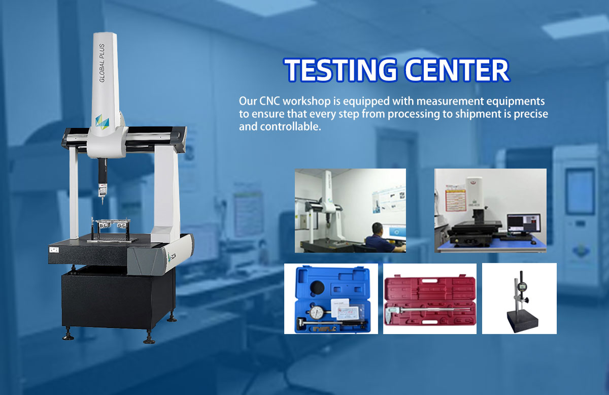
HEXAGON CMM equipment is available for dimensional measurement of appropriate features, and full-dimensional inspection reports can be supplied according to project requirements.
For robot components containing important mating relationships, inspection planning can focus on the dimensions that directly affect assembly rather than only measuring easily accessible external dimensions.
Manufacturing Item | Zhongyi Precision Capability |
|---|---|
Main Process | Precision 5-Axis CNC Machining |
Manufacturing Type | Custom Manufacturing to Drawing |
Factory Experience | 12+ Years |
Production Facility | 5,000+ m² |
Production Equipment | 60+ Units |
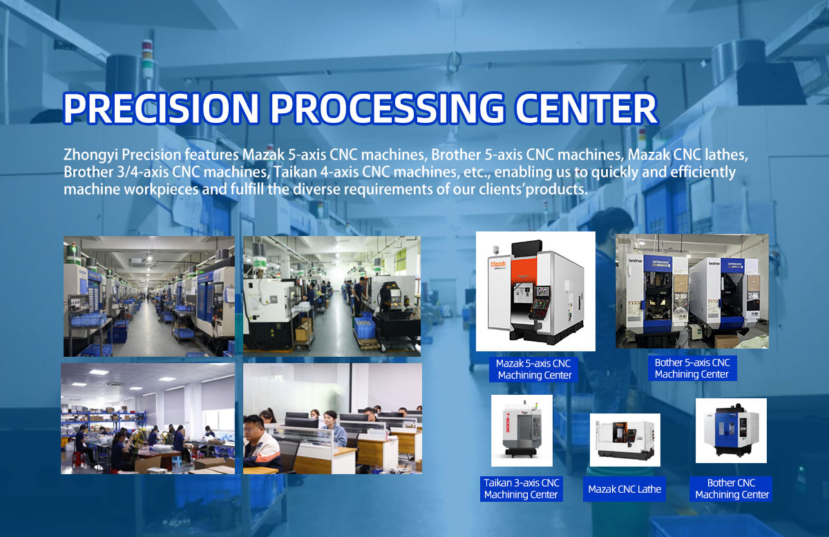
CNC Equipment Brands | Mazak, Brother, Taikan |
CMM | HEXAGON CMM |
Standard Machining Tolerance | Typically ±0.01 mm to ±0.05 mm |
Critical Tolerance Capability | Down to 0.001 mm where geometry, material and process conditions permit |
Production Stage | Prototype to Mass Production |
Prototype Lead Time | Typically 7–15 Business Days |
Production Lead Time | Typically 15–30 Business Days |
Inspection | First Article, In-Process and Final Inspection |
Tolerance capability must always be evaluated against the individual drawing. A capability value should not be interpreted as a blanket tolerance that applies automatically to every feature of every component.
A robot joint end cap normally works together with several neighboring components.
Depending on the joint architecture, these may include:
Electric motor
Harmonic reducer
Planetary reducer
Bearing assembly
Encoder
Output shaft
Joint housing
Fasteners
Cable system
Sealing elements
For this reason, dimensional relationships on an end cap can affect how the complete joint is assembled.
When drawings identify critical mating dimensions, we can use them as priority characteristics during process planning and inspection.
This approach is applicable to customized components used in humanoid robot shoulder, elbow, wrist, hip, knee and ankle joint systems as well as other compact robotic actuator architectures.
Early prototypes are often used to confirm fit, assembly sequence, cable clearance and mechanical interfaces before a robot joint design is frozen.
At this stage, customers can submit revised CAD files as their actuator design evolves.
After prototype approval, small production batches can be used for engineering builds and system-level testing.
Manufacturing feedback collected during the prototype phase can be carried into the pilot batch.
For recurring production, attention shifts toward controlled workholding, stable machining sequences, documented inspection and batch-to-batch dimensional consistency.
Customers therefore do not need to treat prototype machining and production machining as completely unrelated sourcing activities.
A useful RFQ contains more than a 3D model.
For faster engineering review, send as much of the following information as available:
STEP, STP, X_T or other 3D CAD file
2D manufacturing drawing
Material specification
Quantity
Critical tolerances
GD&T requirements
Surface finish requirement
Surface treatment
Thread specifications
Inspection requirements
Prototype or production status
Required delivery date
Where the 2D drawing identifies bearing fits, datum systems or geometric tolerances that are not defined in the 3D model, please include both files.
Standard components are useful only when the mechanical interface has already been standardized.
Humanoid robot development is different. Joint diameter, motor selection, reducer architecture, torque requirement, weight target and packaging constraints can vary significantly between robot platforms.
Drawing-based CNC manufacturing allows engineers to retain control over:
Overall envelope
Wall thickness
Mounting pattern
Bearing interfaces
Hole locations
Internal clearance
Weight-reduction geometry
Datum structure
Surface finish
Assembly method
Instead of modifying a robot design around a stock end cap, the component is manufactured around the approved robot design.
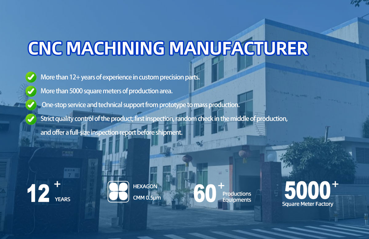
Our Shenzhen facility combines precision CNC equipment with dimensional inspection for customer-specific components.
The current production capability includes more than 60 units of equipment across a 5,000+ m² manufacturing area, with machining equipment from Mazak, Brother and Taikan and inspection support using HEXAGON CMM.
For robotics projects, this allows machining and dimensional verification to remain connected throughout the production process.
We can support:
One-off engineering parts
Prototype batches
Design revisions
Low-volume production
Repeat orders
Production-scale quantities
The manufacturing route is selected according to the drawing, material, quantity and inspection requirements of each project.
If you already have a joint end cap, actuator cover or related robot component in development, send us the drawing instead of trying to match it to a standard product.
Our team can review the geometry, material, tolerances and quantity before preparing the manufacturing quotation.
Recommended RFQ files: 3D CAD + 2D drawing
Useful information to include: material, quantity, critical dimensions, finish, inspection requirements and target delivery date.
Custom robot parts are manufactured according to customer specifications.
Yes. STEP or STP files can be used for geometry review and machining preparation. When the component contains critical tolerances, GD&T, special threads or inspection requirements, a 2D drawing should also be provided because these requirements may not be fully defined in the 3D model.
It depends on part geometry. A simple end cap may not require 5-axis machining. For components containing features on several orientations, complex profiles or closely related multi-face features, 5-axis machining can reduce the number of setups and help maintain feature-to-feature relationships.
Yes, where the geometry provides adequate tool access. Internal pockets, bores, mounting features and external contours can be included in the machining plan according to the CAD model.
Tolerance should be assigned according to function rather than applying the tightest tolerance to every dimension. Critical interfaces may require closer control, while non-functional exterior surfaces can often use wider tolerances. Your drawing requirements can be reviewed before quotation.
Thin-wall features can be machined, but the achievable wall thickness and tolerance depend on part size, geometry, material removal, tool access and rigidity. Thin sections should therefore be evaluated from the actual CAD model.
Aluminum components can receive anodizing or other compatible surface treatments when specified. Areas with close fits or critical dimensions should be identified on the drawing so the impact of the coating can be considered.
Dimensional inspection is part of the quality process, and full-size inspection reports can be provided according to project requirements. Critical features and reporting requirements should preferably be identified during the RFQ stage.
Yes. Prototype machining is suitable for engineering programs that require design iterations before production release. Clearly identifying drawing and CAD revision numbers helps prevent outdated versions from entering production.
Yes. In addition to joint end caps, our machining capability can be applied to drawing-defined joint housings, actuator components, reducer-related housings, motor interfaces, sensor mounts and other precision robotic components.
Quotation is influenced by material, blank size, machining time, number of setups, tolerance requirements, geometric tolerances, surface treatment, inspection requirements and order quantity. Sending both the 3D model and complete manufacturing drawing provides the best basis for an accurate quotation.