
English ![]()

No. 7, Tianyang 6th Road, Dongfang Community, Songgang Street, Bao'an District, Shenzhen, Guangdong, China(518100)
Views: 0 Author: Site Editor Publish Time: 2026-10-27 Origin: Site
Achieving high depth-to-diameter (D:d) ratios in steel components pushes standard manufacturing equipment to its absolute breaking point. Improper execution carries severe financial and operational risks. You face high scrap rates, catastrophic tool breakage inside expensive billets, hole oversize, and unacceptable surface finishes that fail compliance in aerospace, medical, or energy sectors. Standard setups struggle with these demands because they lack the rigidity and fluid dynamics required for deep material removal. However, modern deep hole CNC machining offers a proven solution. By utilizing specialized tooling, high-pressure coolant systems, and strict process controls, machinists can produce precise, repeatable deep bores in even the toughest steel alloys. This approach eliminates the guesswork, ensuring your critical components meet exact specifications without destroying tooling or wasting raw material.
D:d Ratio Dictates the Approach: Standard twist drills fail past a 10:1 depth-to-diameter ratio; successful deep hole machining in steel requires specialized gun drilling or BTA (Boring and Trepanning Association) systems.
Chip Evacuation is the Primary Failure Point: Without high-pressure, through-tool coolant systems, steel chips will pack out, leading to immediate heat buildup, tool deflection, and breakage.
Advanced Setup is Non-Negotiable: Utilizing multi-axis CNC machining for complex bores minimizes setup changes, directly reducing concentricity errors and runout in critical components.
Material Selection Influences Tooling: Machining 304/316 stainless steel requires vastly different feed, speed, and tooling geometries compared to carbon steels due to work-hardening risks.
Machinists classify hole depth using the depth-to-diameter (D:d) ratio. Ratios under 5:1 represent standard drilling operations. Most conventional twist drills handle these depths without specialized setups. Ratios hitting 10:1 cross into deep hole territory. At this threshold, standard chip evacuation methods begin to fail. Ratios exceeding 20:1 classify as extreme deep hole operations, requiring entirely different machining philosophies.
The physics of machining change exponentially as the D:d ratio increases. Tool rigidity drops drastically as the drill length extends. A longer tool acts like a lever, amplifying any lateral forces at the cutting tip. Torque transfer also becomes highly inefficient. The spindle applies rotational force at the tool base, but the cutting edge experiences resistance deep inside the material. This torsional strain causes long drills to wind up like a spring. When the cutting edge finally bites into the steel, that stored energy releases, causing the tool to twist, vibrate, or snap if feed rates exceed physical limits.
Steel introduces specific mechanical challenges during deep hole operations. High tensile strength requires immense cutting forces to shear the material. These forces generate massive amounts of heat at the cutting zone. Certain alloys present additional hurdles. Austenitic stainless steels, for example, work-harden rapidly. If the cutting tool rubs against the material instead of slicing through it, the steel surface hardens instantly. This hardened layer destroys the tool edge on the next rotation.
Standard flood coolant completely fails at depth. Coolant sprayed from outside the hole cannot penetrate past the exiting chips. The cutting zone becomes starved of lubrication. Friction spikes immediately. Without fluid to carry away thermal energy, the tool overheats, loses its temper, and fails catastrophically inside the bore. The heat generated at the cutting tip can easily exceed 600 degrees Celsius if coolant flow is interrupted, permanently altering the metallurgy of the workpiece.
Common CNC milling centers offer excellent versatility but possess inherent limitations for deep boring. Most standard mills lack the structural rigidity required to keep a long boring bar perfectly straight under heavy cutting loads. The machine column may flex microscopically, causing the hole to wander off-center. Z-axis travel limits also restrict the maximum length of the tool that can fit between the spindle and the workpiece.
Coolant pressure remains the most significant limitation. Standard mills often feature coolant pumps rated for 300 PSI or less. Deep hole operations in steel require high-pressure systems, frequently exceeding 1,000 PSI. This hydraulic force is necessary to blast heavy steel chips out of a long, restrictive channel. Attempting extreme D:d ratios on a standard mill without process modifications usually results in broken tools and scrapped parts.
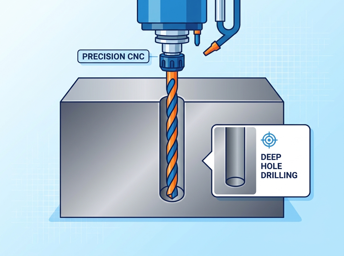
Engineers primarily rely on two distinct systems for deep hole operations: gun drilling and BTA (Boring and Trepanning Association) drilling. Gun drilling utilizes a single-lip cutting tool with an internal coolant channel. High-pressure coolant travels down the center of the tool and flushes chips out through an external V-shaped flute along the tool body. This method excels for smaller diameters ranging from 1mm to 50mm.
BTA drilling operates on the opposite principle. It uses an internal chip exhaust system. A pressure head seals against the workpiece, and coolant flows around the outside of the drill tube. The pressure forces chips back through the hollow center of the tool. BTA systems handle larger diameters effectively, typically starting around 20mm and extending well beyond 200mm. BTA drilling removes material much faster than gun drilling but requires highly specialized, dedicated machinery capable of pumping 50 to 100 gallons of coolant per minute.
| Feature | Gun Drilling | BTA Drilling |
|---|---|---|
| Optimal Diameter Range | 1mm to 50mm | 20mm and above |
| Chip Exhaust Path | External (V-flute on tool body) | Internal (Through the hollow tool center) |
| Coolant Delivery | Internal (Through tool center) | External (Around the tool tube) |
| Material Removal Rate | Moderate | High (Up to 10x faster than gun drilling) |
| Equipment Requirements | Can adapt to standard CNC with high-pressure coolant | Requires dedicated BTA drilling machines |
Executing CNC drilling for custom metal parts requires matching the equipment to the hole depth. Standard CNC milling centers attempt deep holes using peck drilling cycles (G83). The machine drives the drill into the steel for a short distance, then fully retracts it to clear chips. This cycle repeats until reaching the final depth. Peck drilling prevents chip packing but significantly increases cycle times. It also accelerates tool wear because the cutting edge constantly re-engages the work-hardened material at the bottom of the hole.
Dedicated deep hole drilling machines do not peck. They feed the tool continuously from start to finish. Adapting standard CNC centers for continuous deep hole tasks requires strict adherence to a specific setup sequence to ensure success:
Spot drill the surface to establish the true position of the hole.
Drill a pilot hole 1.5x to 2x the diameter deep using a standard, rigid carbide drill.
Enter the pilot hole with the deep hole drill at a low RPM (e.g., 300 RPM) and a slow feed rate.
Engage the high-pressure through-spindle coolant and increase the RPM to the designated cutting speed.
Feed continuously to the final depth without pecking to maintain chip flow.
Reduce the RPM and turn off the coolant before retracting the tool from the bore.
Turning deep blind holes on a lathe presents a different set of mechanical variables. In turning operations, the workpiece spins while the cutting tool remains stationary. This dynamic naturally promotes better concentricity compared to milling. However, blind holes trap chips at the bottom of the bore. Gravity cannot assist in chip removal, making horizontal lathe operations particularly challenging.
Performing stainless steel precision CNC turning for deep blind holes requires aggressive chip management. Threading or tapping these holes at depth adds extreme complexity. Machinists must select appropriate tool coatings, such as Titanium Aluminum Nitride (TiAlN), to resist the intense heat generated by threading stainless steel. Specialized high-pressure coolant nozzles must direct fluid precisely at the cutting edge to prevent chips from welding to the hole base. If chips weld to the bottom, the tap will crash into them and shatter instantly.
Chip pack-out remains the most common cause of tool failure in deep bores. When cutting steel, the tool generates continuous ribbons or broken chips of metal. If these chips do not exit the hole immediately, they jam inside the tool flutes. This creates a solid mass of metal known as pack-out. Friction spikes instantly. The tool stops cutting and starts rubbing, leading to immediate breakage and hole oversize. You can often hear a distinct change in the machining pitch—a sudden, high-pitched squeal—right before a pack-out destroys the tool.
Preventing pack-out requires programmable high-pressure through-spindle coolant. Pressures of 1,000 PSI or higher act as a hydraulic ram. The fluid breaks the steel chips into manageable pieces and continuously flushes them out of the bore. Controlling the chip size through proper feed rates and specialized chip-breaking insert geometries is equally important. Long, stringy chips will tangle and cause pack-out regardless of coolant pressure.
Heat causes thermal expansion in both the cutting tool and the steel workpiece. As temperatures rise, the tool expands outward, cutting a larger diameter than intended. The workpiece also expands, distorting the hole geometry. For example, a 50mm diameter steel boss might expand by 0.02mm during heavy machining. If you bore it to the exact tolerance while hot, it will shrink undersize when it cools down.
Tool deflection, or wandering, occurs when lateral forces push the drill off its center axis. A long drill bit naturally wants to bend under pressure. Mitigating deflection requires precise pilot holes to guide the tool during initial entry. Guide bushings provide physical support near the cutting zone. Rigid workholding prevents the steel billet from shifting under heavy machining loads. Any movement in the workpiece translates directly into a crooked bore with high Total Indicator Runout (TIR).
Deep bores often suffer from poor surface finish. Chatter occurs when the tool vibrates against the hole wall, leaving a rough, wavy pattern. Chip scoring happens when hard steel chips drag along the finished surface as they exit the hole, leaving deep scratches that compromise O-ring seals or bearing fits.
Mitigation strategies often involve secondary operations. Achieving tight micro-inch finishes usually requires honing, reaming, or roller burnishing. Each method serves a specific functional requirement for the final component.
| Secondary Operation | Mechanism | Best Application |
|---|---|---|
| Reaming | Uses a multi-fluted cutting tool to shave a tiny amount of material from the bore wall. | Sizing holes to precise diametric tolerances quickly. |
| Honing | Uses expanding abrasive stones to grind the bore wall, creating a cross-hatch pattern. | Hydraulic cylinders where the cross-hatch retains oil for lubrication. |
| Roller Burnishing | Uses hardened steel rollers to compress the metal surface, flattening microscopic peaks. | Creating mirror-like finishes and work-hardening the bore for wear resistance. |
Traditional manufacturing often requires moving a steel component between multiple machines to complete complex hole patterns. Every time a machinist unclamps and reclamps a part, alignment errors occur. This phenomenon, known as tolerance stacking, ruins concentricity in deep bores. A hydraulic manifold, for instance, might have dozens of intersecting deep holes that must align perfectly to prevent fluid leaks.
Implementing multi-axis CNC machining for complex bores eliminates these setup changes. A 5-axis machine utilizes a rotating trunnion to tilt the steel billet, allowing the spindle to drill intersecting deep holes or angled bores without ever removing the part from the fixture. This mathematical reduction in tolerance stacking directly reduces runout. A single setup ensures that the geometric relationship between multiple deep bores remains perfectly intact from the first hole to the last.
Modern CNC controllers utilize advanced sensors to monitor the machining process in real time. Spindle load monitoring tracks the amount of electrical current required to turn the tool. As a drill dulls or chips begin to pack out, the spindle must work harder. The controller detects these micro-spikes in torque instantly.
Adaptive control systems respond to this sensor data automatically. Machinists can program macro variables that trigger an alarm if the spindle load exceeds 110% of the baseline cutting load. If the system detects a dangerous torque spike that precedes tool breakage, it automatically reduces the feed rate or retracts the tool to clear the chips. Vibration sensors mounted on the spindle housing detect chatter before it damages the surface finish. These technologies allow machines to run deep hole operations unattended with a high degree of safety.
Procuring deep hole machining services requires a strict evaluation of a vendor's equipment. Standard job shops cannot handle extreme D:d ratios in steel. You must verify specific machine capabilities. Request documentation on their through-spindle coolant pressure; anything under 1,000 PSI will struggle with deep steel bores. Check if they utilize dedicated deep hole machinery like gun drills or BTA systems, rather than just adapting standard mills. Inspect the machine castings. Heavy, rigid cast-iron bases absorb vibration and maintain the alignment necessary for deep boring.
A vendor's tooling expertise dictates their success rate. Different steel grades behave entirely differently under the cutter. Machining 4140 chromoly steel requires different edge prep than machining 17-4 PH stainless or 316L. Evaluate the vendor's approach to custom tool grinding. Shops that grind their own gun drill tips can optimize the cutting angles for specific alloys, improving chip breaking and extending tool life. Ask about their insert selection criteria for BTA drilling, specifically regarding heat-resistant coatings and chip-breaker geometries.
Verifying the quality of a deep hole requires specialized metrology. Standard calipers cannot measure the bottom of a 400mm bore. A qualified shop must possess the right inspection tools. Dial bore gauges with extension rods measure the internal diameter at various depths to check for taper or bell-mouthing. Ultrasonic wall thickness measurement tools verify concentricity by ensuring the hole remains perfectly centered within the outer diameter of the part, detecting if the drill bowed in the middle. Borescopes provide visual inspection of the internal surface finish, allowing quality control teams to identify chip scoring or chatter marks deep inside the component.
Deep hole CNC machining in steel is highly feasible, but it remains an unforgiving process. It strictly prohibits corner-cutting in tooling selection, coolant delivery, or setup rigidity. Success depends entirely on managing chip evacuation and controlling thermal expansion. When executed correctly with specialized equipment, manufacturers can achieve extreme depth-to-diameter ratios with exceptional precision.
Procurement and engineering teams must filter out machine shops that rely solely on standard peck drilling for high D:d ratios. Prioritize vendors equipped with dedicated high-pressure coolant systems, specialized gun drilling or BTA machinery, and multi-axis capabilities to consolidate setups.
To move forward with your deep hole machining requirements, take the following actions:
Submit your CAD models for a comprehensive Design for Manufacturability (DFM) review.
Require the vendor to validate hole tolerances against your specific steel alloy selection.
Request a detailed breakdown of their proposed tooling paths and coolant strategies.
Specify your surface finish requirements and ask for their secondary operation plan.
A: While standard drills max out around 10:1, specialized gun drilling can achieve ratios of 100:1 or more, depending on the alloy and coolant pressure.
A: Flood coolant cannot reach the cutting edge at depth; through-tool coolant provides lubrication, cooling, and the hydraulic force necessary to evacuate chips and prevent pack-out.
A: Maintain constant feed rates to prevent work hardening, use sharp carbide tooling, and ensure aggressive chip evacuation to keep the cutting zone cool.
A: Standard mills can perform moderate deep hole drilling using peck cycles and pilot holes, but they lack the high-pressure coolant capabilities required for extreme D:d ratios in high-strength steel.
A: Gun drilling uses external chip exhaust (V-flute) for smaller diameters, whereas BTA drilling utilizes internal chip exhaust, making it superior for larger-diameter, high-production bores.
A: By utilizing specialized flat-bottom drills and high-pressure coolant to prevent chip recutting, followed by secondary boring or reaming where necessary for precision tolerances.
A: Hole oversize is typically caused by tool deflection (wandering), asymmetrical drill sharpening, or inadequate chip evacuation causing the drill to vibrate and cut oversized.


