
English ![]()

No. 7, Tianyang 6th Road, Dongfang Community, Songgang Street, Bao'an District, Shenzhen, Guangdong, China(518100)
Views: 0 Author: Site Editor Publish Time: 2026-09-30 Origin: Site
Robotics hardware development carries exceptionally high stakes. Kinematic accuracy, strict weight constraints, and heavy dynamic loads leave absolutely no room for manufacturing compromises. You are likely moving past the initial prototyping phase. You now face the challenge of transitioning a validated design into pilot runs or scaled production. This leap requires advanced precision manufacturing. Basic rapid prototyping simply cannot meet stringent structural demands. Securing reliable CNC machining services requires moving beyond basic quotes. You must carefully evaluate a manufacturing partner’s specialized capabilities. Look closely at their 5-axis machinery, deep Design for Manufacturing (DFM) expertise, and rigorous quality control frameworks. We will explore how to navigate tolerance stack-ups, optimize material selection, and mitigate implementation risks. You will learn actionable strategies to ensure your complex robotic assemblies perform flawlessly in the real world.
Precision is paramount: Robotic joints, custom actuators, and chassis require tight tolerances (often ±0.005mm) to prevent cumulative kinematic errors.
Technology matching: 5-axis CNC machining for complex robotics components reduces setup transfers, mitigating alignment risks on multi-faceted parts.
Vendor evaluation criteria: Reliable partners must offer verifiable CMM (Coordinate Measuring Machine) inspection, robust DFM feedback, and clear scalability from low-volume prototypes to end-to-end production.
Robotics engineers constantly battle physics. Every gram of payload matters. Every micron of deviation impacts final positioning. Transitioning from a digital CAD file to a physical assembly uncovers hidden manufacturing hurdles. Understanding these engineering realities helps you design better components.
Micro-deviations compound rapidly across multi-axis assemblies. A single robotic arm might feature six distinct rotary joints. If each joint housing deviates by just 0.02mm, the final end-effector position could miss its target by several millimeters. This phenomenon severely impacts repeatability and accuracy. Standard machining often fails to control these interacting surfaces. You must specify exact geometric relationships. True position, concentricity, and perpendicularity often matter more than simple dimensional tolerances. Controlling these variables prevents kinematic errors from compounding down the kinetic chain.
Mobile robots and industrial arms require high payload-to-weight ratios. Engineers achieve this through aggressive thin-wall machining and complex pocketing. However, machining thin structural webs introduces significant challenges. Cutting forces cause thin walls to deflect. This chatter ruins surface finishes and destroys dimensional accuracy. Advanced programmers counteract this by utilizing specialized high-speed tool paths. They step down gradually, balancing material removal rates against structural integrity. You achieve lighter robotic chassis without sacrificing vital stiffness.
Different materials react unpredictably under heavy cutting forces. Hard-to-cut alloys pose distinct problems. Titanium offers incredible strength but generates intense heat at the cutting edge. This accelerates tool wear and increases cycle times. Conversely, aerospace-grade aluminum and engineering plastics like PEEK carry thermal warping risks. Aggressive machining releases internal stresses. The material can warp unexpectedly after you remove it from the fixture. Managing this volatility requires strategic roughing passes. The shop must allow the material to rest and relieve stress before executing the final precision finishing cuts.
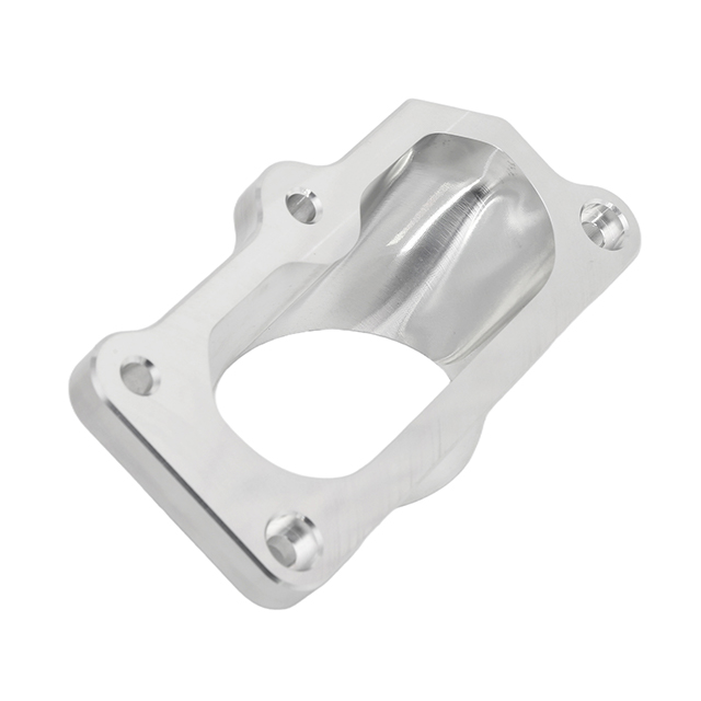
No single machine tool solves every manufacturing problem. Selecting the correct machining technology dictates the success of your robotic components. Proper technology matching minimizes errors and optimizes cycle times.
Modern robotics rely on highly contoured, organic geometries. Common use cases include multi-directional joint housings, complex end-effectors, and contoured sensor mounts. Utilizing 5-axis CNC machining for complex robotics components solves severe fixturing challenges. The primary benefit lies in single-setup machining. A traditional 3-axis mill requires an operator to manually flip the part multiple times. Every flip introduces a tiny alignment error. Continuous 5-axis centers rotate the part and the tool simultaneously. This eliminates repositioning errors. You guarantee perfect concentricity across opposing bores and strict parallelism across complex faces.
Robotic frameworks require massive rigidity. Primary use cases include thick base plates, heavy-duty motor brackets, and main chassis frames. Producing these elements demands robust equipment. Professional CNC milling robotics parts guarantees high material removal rates for rigid structural components. Heavy casting-like designs are quickly hollowed out into lightweight, ribbed structures. High-torque spindles plow through solid billets while maintaining strict flatness and perpendicularity. This provides a rock-solid foundation for subsequent dynamic movements.
Rotational movement forms the heart of robotic articulation. Primary use cases involve custom drive shafts, planetary actuator housings, and precision locating pins. CNC turning centers rotate the raw stock against a stationary cutting tool. This achieves exceptionally tight diametrical tolerances necessary for high-speed rotational movement. Mill-turn centers combine lathe operations and milling tools in one machine. You can turn a precise shaft and immediately mill a complex spline or keyway without ever moving the part.
Your material choices directly dictate machine time, tooling costs, and structural performance. A balanced approach prevents unnecessary manufacturing expenses. We must evaluate materials based on strength, weight, and machinability.
Aluminum remains the undisputed industry standard for structural limbs and brackets. It offers an exceptional balance of high machinability, lower raw costs, and a superb strength-to-weight ratio. The 6061-T6 grade provides excellent corrosion resistance and accepts anodizing beautifully. When you need extreme stress resistance, 7075-T6 rivals the strength of some steels while weighing significantly less.
Certain robotic nodes endure massive shear forces. Titanium and stainless steels become critical for high-stress nodes, custom gearboxes, and harsh operating environments requiring extreme corrosion resistance. However, you must confront the implementation reality. These metals harden as they are cut. This slower machining time dictates noticeably higher costs. You should use them strictly where absolute necessity demands it, rather than applying them globally.
Plastics play a crucial, often overlooked role in robotics. Engineering polymers are frequently utilized for electrical insulation, lightweight gear trains, and low-friction wear surfaces. Delrin (POM) machines beautifully and provides natural lubricity for sliding mechanisms. PEEK withstands high temperatures and aggressive chemicals, though it requires strict environmental controls during machining to prevent dimensional shifts.
Table 1: Material Selection Matrix for Robotics Manufacturing
| Material Grade | Primary Robotic Application | Machinability (1-10) | Key Benefit |
|---|---|---|---|
| Aluminum 6061-T6 | Chassis, mounting plates, brackets | 9 | Highly cost-effective, easy to anodize |
| Aluminum 7075-T6 | High-stress structural arms | 8 | Aircraft-grade strength-to-weight ratio |
| Titanium (Ti-6Al-4V) | Extreme load nodes, micro-gears | 4 | Exceptional strength, non-magnetic |
| Stainless Steel 316L | Marine/medical robotic housings | 5 | Superior corrosion resistance |
| Delrin (POM) | Bushings, low-friction sliders | 10 | High machinability, natural lubricity |
| PEEK | Electrical insulators, high-temp joints | 7 | High thermal and chemical stability |
Moving from a digital CAD model to a physical robot requires a highly capable partner. You are evaluating a decision-stage framework, not just hunting for the lowest hourly rate. A true partner actively improves your design.
DFM (Design for Manufacturing) Integration: The shop should never execute an upload blindly. Their engineers must scrutinize your files. They will flag un-machinable internal radii that require impossibly small tools. They should suggest tolerance relaxations where perfectly safe, reducing your final bill. They will optimize tool paths to drastically reduce cycle time.
Quality Assurance & Inspection Protocols: Trust requires verifiable data. You must require comprehensive documentation. Demand detailed CMM reports, First Article Inspection (FAI) reports, and raw material certificates. You should actively look for ISO 9001 or AS9100 compliance. These certifications ensure repeatable, strict quality control procedures are deeply embedded in their daily operations.
End-to-End Scalability: Your project lifecycle will evolve. Assess the vendor's mechanical ability to handle iterative prototyping runs (1-10 units). They must accomplish this without bottlenecking when you suddenly transition into low-volume production (100-1,000+ units). A flexible shop scales their fixturing and programming alongside your growing demands.
Robotic parts frequently run over budget. These cost spikes rarely stem from raw material prices. Instead, they originate from poor tolerancing habits and misunderstood manufacturing realities. Avoiding these common pitfalls protects your project timeline.
Engineers often apply blanket tight tolerances to an entire part out of caution. This creates a severe risk of exponential cost increases. Default tight tolerances applied to non-critical surfaces force machinists to slow down drastically. Action: Apply Geometric Dimensioning and Tolerancing (GD&T) strictly to mating surfaces, bearing press-fits, and kinematic locating pins. Let non-mating surfaces breathe with looser standard tolerances.
Clarify exactly when standard as-machined finishes suffice. An Ra 3.2 (125 µin) finish works perfectly well for internal mounting brackets. Pushing for an Ra 1.6 or finer on every surface adds unnecessary machine passes. Identify when secondary operations become truly required. Anodizing, bead blasting, or precision grinding should only be specified for critical wear resistance or external aesthetics.
Chart: Surface Finish Guidelines vs. Functional Needs
| Finish Roughness (Ra) | Manufacturing Method | Appropriate Robotic Application |
|---|---|---|
| Ra 3.2 µm (125 µin) | Standard high-speed milling | Internal frames, hidden motor brackets |
| Ra 1.6 µm (63 µin) | Fine finishing passes | Static mating surfaces, external covers |
| Ra 0.8 µm (32 µin) | Slow finishing / light grinding | O-ring grooves, tight locating pins |
| Ra 0.4 µm (16 µin) | Precision grinding / lapping | Dynamic bearing journals, fluid seals |
Complex 5-axis setups require extensive, meticulous CAM programming. Transparent manufacturing partners will always define exact lead times based on actual material availability and current machine scheduling. They do not sell you on best-case hypotheticals. Plan your assembly schedule around realistic programming and fixturing blocks.
Securing reliable manufacturing dictates the functional success of your final robot. Precision hardware leaves no room for guesswork. Sourcing CNC machining robotic parts acts as a strategic partnership, not a simple transactional purchase. When you treat your manufacturer as an extension of your engineering team, you unlock massive efficiencies.
Evaluate multi-axis capabilities to minimize setup errors on complex joints.
Leverage comprehensive DFM reviews to eliminate unnecessary machining costs.
Apply strict GD&T only where kinematic accuracy truly demands it.
Demand verifiable CMM reports to guarantee part compliance before assembly.
Your next step involves practical validation. We advise hardware teams to request a comprehensive DFM review alongside initial RFQs. This immediately tests the vendor’s engineering acumen. We invite engineers to submit their CAD files today for an expert DFM analysis and a highly precise machining quote.
A: Standard CNC machining typically holds ±0.1mm. However, critical robotic joints and bearing press-fits frequently require high-precision tolerances ranging from ±0.01mm to ±0.005mm. You can readily achieve these tight metrics via well-calibrated CNC centers and rigorous thermal control.
A: You need 5-axis capabilities when a part features geometries on more than two sides, complex undercuts, or sweeping contoured surfaces. Organic robotic limbs heavily benefit from 5-axis routing, as manual re-fixturing would easily compromise strict alignment.
A: Cost is primarily driven by raw material price and machinability. Machinability dictates tool wear and overall cycle time. Aluminum is highly cost-effective and cuts quickly. Conversely, Titanium significantly increases tool wear and consumes more machining hours, heavily driving up your final cost.


