
English ![]()

No. 7, Tianyang 6th Road, Dongfang Community, Songgang Street, Bao'an District, Shenzhen, Guangdong, China(518100)
Views: 0 Author: Site Editor Publish Time: 2026-08-12 Origin: Site
Industrial manufacturing requires processes that can reliably bridge the gap between rapid prototyping and high-fidelity, low-to-medium volume production. Decision-makers increasingly rely on the rapid turnaround time and material flexibility of CNC machining to meet these demands without compromising dimensional accuracy. Selecting the wrong manufacturing method for critical components leads to compliance failures, unacceptable rejection rates, and inflated unit costs. Decision-makers must evaluate whether the upfront programming and setup costs of machining are justified by the required tolerances, material properties, and end-use environment. This guide breaks down the top five industrial applications for subtractive manufacturing, analyzing the specific success criteria, material constraints, and implementation risks associated with each sector to inform vendor selection and process viability.
Tolerance and Repeatability: Precision CNC machining remains the standard for applications requiring micron-level accuracy and strict geometric dimensioning and tolerancing (GD&T), particularly in medical and aerospace sectors.
Material Versatility vs. Machinability: While capable of processing everything from advanced polymers to titanium, material selection directly impacts tool wear, cycle times, and total cost per part.
Manufacturing Modalities: CNC machining delivers value across direct manufacturing (end-use parts), indirect manufacturing (tooling and molds), and hybrid processes (finishing 3D printed or cast components).
Regulatory Compliance: For highly regulated industries, the value of a CNC partner is measured not just in machine capabilities, but in traceability, quality management systems (e.g., AS9100, ISO 13485), and documented inspection processes.
Engineers must define baseline requirements before committing to subtractive manufacturing. You should focus specifically on surface finish requirements and geometric dimensioning and tolerancing (GD&T). Assess your required Ra (Roughness Average) values for mating surfaces. A standard milled finish might yield a 125 Ra, but O-ring grooves and bearing journals often demand a 32 Ra or better. Subtractive methods maintain a continuous grain structure in metal billets, providing superior structural integrity compared to the layered, anisotropic nature of additive methods. You must also review your tight tolerances. Many industrial applications demand tolerances of ±0.0005 inches. Rigid machine setups and high-quality carbide tooling achieve these numbers consistently across production batches.
Evaluate your project scope to determine the correct manufacturing modality. You will use direct manufacturing to produce final end-use components straight from raw bar stock or plate. Alternatively, you can leverage indirect manufacturing. This involves machining custom molds, extrusion dies, and assembly jigs. Machining P20 tool steel or aluminum mold bases supports high-volume injection molding operations. Finally, consider hybrid processes. Manufacturers often machine specific features into rough 3D-printed or cast components. You can cast a near-net shape to save material, then mill the critical mounting faces to achieve exact flatness and true position.
Compare multi-axis milling, turning, and Swiss-style machining against alternative methods. Direct Metal Laser Sintering (DMLS) offers complex internal geometries but lacks surface finish quality and requires extensive post-processing. Injection molding scales exceptionally well but demands massive upfront tooling investments and long lead times. Die casting suits high volumes but suffers from internal porosity issues that compromise strength. Subtractive machining excels in industrial prototyping and low-to-medium volume production. It provides exact material properties during the testing phase, ensuring your prototype behaves exactly like the final production unit.
Analyze the cost-volume curve for your specific project. Subtractive methods absorb high initial setup and programming costs. CAM programming, fixture design, and machine setup require skilled labor upfront. However, the process offers lower per-unit costs at medium volumes. It scales better than additive manufacturing for batches ranging from 50 to 5,000 units. Eventually, casting or molding outpaces machining at mass-production scales. You must find the break-even point for your specific geometry. A complex part with deep pockets might be cheaper to cast at 2,000 units, while a simple bracket might remain cheaper to machine up to 10,000 units.
Aerospace manufacturing demands zero margin for error. Core components include turbine blades, landing gear fittings, hydraulic manifolds, and engine housings. Engineers also machine custom structural airframes from solid billets to eliminate fasteners and reduce weight. Success criteria focus heavily on exceptional strength-to-weight ratios. Parts must exhibit extreme fatigue resistance under cyclical loading and severe temperature fluctuations. Furthermore, facilities must adhere to strict AS9100 quality standards. Traceability remains mandatory for every single flight-critical component. You must track the material heat lot from the mill all the way to the final installed part.
Aerospace applications rely on advanced superalloys and high-strength aluminums. Manufacturers use titanium alloys like Ti-6Al-4V for structural components due to its excellent corrosion resistance and strength. Inconel 718 dominates high-temperature zones inside jet engines. These materials present severe machinability challenges. They work-harden rapidly, cause extreme tool wear, and require highly rigid machine setups to prevent chatter. Conversely, engineers specify lightweight aluminum for less extreme environments. You must balance aggressive feed rates against tool degradation when cutting 7075-T6 aluminum. High-speed machining (HSM) techniques utilize light radial depths of cut and high feed rates to clear chips quickly and manage heat.
Aerospace Material Machinability Comparison
| Material | Primary Aerospace Application | Machinability Rating | Common Tooling Requirement |
|---|---|---|---|
| Aluminum 7075-T6 | Structural frames, wing ribs | Excellent | Uncoated or ZrN coated carbide |
| Titanium Ti-6Al-4V | Landing gear, fasteners | Poor | AlTiN coated carbide, high-pressure coolant |
| Inconel 718 | Turbine blades, exhaust components | Very Poor | Ceramic inserts, rigid workholding |
| Stainless Steel 17-4 PH | Actuators, high-strength brackets | Fair | TiAlN coated carbide, moderate speeds |
Aggressive material removal introduces significant implementation risks. Material deformation often occurs during heavy roughing passes. Residual stress inside the raw billet can warp thin-walled aerospace components once you remove the surrounding material. You must mitigate these risks proactively. Specify stress-relief thermal processes between roughing and finishing operations. Implement advanced coolant strategies, such as through-tool high-pressure coolant, to manage heat generation and evacuate chips from deep pockets. Finally, enforce strict first-article inspection (FAI) protocols using Coordinate Measuring Machines (CMM). This guarantees dimensional accuracy before full production begins.
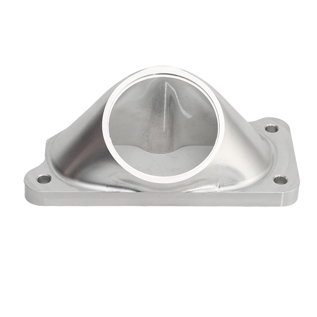
The automotive sector utilizes subtractive manufacturing across multiple stages of vehicle development. Core components include cylinder heads, custom engine blocks, brake calipers, and transmission housings. Engineers also design complex suspension components like control arms and steering knuckles. You must differentiate between rapid prototyping and production. R&D teams use machining for functional testing of new engine geometries. Low-volume production supports high-performance vehicles, heavy-duty trucks, and electric vehicle (EV) platforms. The aftermarket sector also relies heavily on CNC machining for automotive parts to produce custom turbo manifolds and upgraded drivetrain components.
Modern automotive design requires complex geometries to maximize fluid dynamics and minimize weight. 5-axis machining enables these intricate shapes in fluid-routing components. You can manufacture intake manifolds and cylinder head ports without requiring multi-part assemblies. This reduces potential failure points, eliminates leak paths, and improves airflow efficiency. Evaluate the scalability of turning operations as well. Automated lathes with bar feeders support high-volume production of transmission shafts, engine valves, and alignment pins. Live tooling on these lathes allows simultaneous milling and turning, dropping cycle times significantly by finishing the part in a single setup.
Compare machining directly against die casting for automotive parts. Casting remains superior for mass production exceeding 100,000 units. It drops the per-unit cost significantly for engine blocks and transmission cases. However, casting cannot achieve the tight tolerances required for engine internals or bearing journals. Machining serves as a mandatory hybrid process here. Manufacturers follow a specific sequence to achieve final dimensions:
Cast the raw engine block using A356 aluminum to establish the near-net shape.
Load the casting into a horizontal machining center using specialized hydraulic workholding.
Mill the deck surface perfectly flat to ensure proper head gasket sealing.
Bore the engine cylinders to exact diameters, leaving a few thousandths of an inch for final honing.
Drill and tap all mounting holes for the oil pan, water pump, and cylinder head bolts.
Medical manufacturing requires absolute precision, cleanliness, and traceability. Identify core components like orthopedic implants, bone screws, spinal cages, and titanium plates. Facilities also produce surgical instruments, dental abutments, and diagnostic equipment housings. Manufacturers target absolute biological safety and biocompatibility. Zero-defect manufacturing is the baseline expectation, as a failed part can result in severe patient harm. Facilities must maintain strict ISO 13485 compliance to operate in this sector, documenting every step of the manufacturing and inspection process.
Miniature medical components demand specialized equipment. Precision CNC machining often relies on Swiss-style lathes for these applications. These machines handle extreme length-to-diameter ratios perfectly. They guide the material through a guide bushing right at the cutting tool. This eliminates deflection on tiny bone screws that might be 3mm in diameter but 50mm long. Medical parts also require burr-free finishes. Rough edges can cause tissue damage, sever surgical gloves, or promote bacterial colonization. Patient safety depends on flawless surface execution, often requiring secondary operations like electropolishing or manual deburring under microscopes.
Medical Machining Parameters and Requirements
| Component Type | Typical Material | Required Tolerance | Critical Surface Requirement |
|---|---|---|---|
| Bone Screws | Titanium Grade 23 | ±0.0005 inches | Burr-free thread crests |
| Surgical Scalpel Handles | 316L Stainless Steel | ±0.002 inches | Smooth, crevice-free finish |
| Dental Implants | Titanium Grade 4 | ±0.0002 inches | Specific surface roughness for osseointegration |
| MRI Machine Housings | 6061 Aluminum | ±0.005 inches | Non-magnetic properties |
Contamination poses the biggest risk during medical machining. Standard industrial coolants contain sulfur and chlorine, which can leave toxic residues on implants. Failure to meet traceability standards can trigger massive product recalls. You must mandate medical-grade cutting fluids or machine plastics dry. Implement strict lot control for raw materials, keeping material test reports (MTRs) on file indefinitely. Finally, require thorough post-machining passivation. This chemical process uses nitric or citric acid to remove free iron from the surface of stainless steel parts, promoting a passive oxide layer that prevents corrosion inside the human body.
Robotics development moves at a rapid pace, requiring highly customized mechanical components. Core components include end-of-arm tooling (EOAT), custom assembly jigs, and sensor housings. Engineers also design complex robotic joints, harmonic drive housings, and motor mounts. Success criteria focus on high dimensional accuracy. This accuracy ensures kinematic repeatability across millions of cycles on an assembly line. Lightweighting improves motor efficiency, reduces inertia, and increases the payload capacity of the robotic arm. Rapid iteration capabilities allow engineers to test new end-effector designs quickly before deploying them to the factory floor.
Weight reduction drives material selection in robotics. Engineers evaluate lightweight engineering polymers like Delrin (Acetal) and PEEK. These plastics offer low friction, excellent wear resistance, and high dimensional stability. Teams frequently pair polymers with aluminum CNC machining. Aluminum reduces payload strain on robotic arms while maintaining the structural rigidity required for heavy lifting. Precision tolerances matter immensely in gearboxes and drive mechanisms. Tight machining eliminates backlash, ensuring smooth, predictable robotic movements without jitter or positioning errors.
Over-engineering parts remains a common risk in robotics development. Complex internal features lead to excessive machining time and inflated costs. Deep pockets require specialized long-reach tools that are prone to chatter and breakage. You must implement rigorous Design for Manufacturability (DFM) reviews before releasing prints to the shop floor. Simplify geometries wherever possible. Standardize internal radii to match common end-mill sizes (e.g., using a 0.130" radius for a 0.250" end mill). Minimize the need for multiple machine setups by designing parts that can be machined from a single direction, keeping production costs manageable.
Defense and advanced electronics applications operate in harsh, unforgiving environments. Core components include complex heat sinks, RF/EMI shielding enclosures, mil-spec connectors, and ruggedized communication housings. Manufacturers also produce optical housings for targeting systems. Success criteria demand superior thermal conductivity to protect sensitive processors from overheating in enclosed spaces. Environmental sealing prevents moisture, dust, and salt fog ingress. Furthermore, defense contractors must ensure strict compliance with ITAR (International Traffic in Arms Regulations), restricting manufacturing access to authorized personnel and facilities.
Thermal management dictates the material choices for electronic enclosures. Copper offers excellent thermal conductivity but weighs significantly more than aluminum and is gummy to machine. Engineers often machine complex fin geometries into aluminum 6061 heat sinks. This maximizes surface area for heat dissipation while keeping the payload light. RF shielding requires precise mating surfaces. Even microscopic gaps between the lid and the housing can allow electromagnetic interference to escape or enter. Machining ensures these enclosures fit together flawlessly under compression, often incorporating tight-tolerance grooves for conductive O-rings.
Vibration and shock present major risks to electronic housings mounted on vehicles or aircraft. Thin walls designed to save weight might fail under ballistic impact or extreme vibration. You must balance lightweighting goals against structural survivability. Mitigate risks by modeling stress loads in FEA software before machining. Use robust fixturing, such as vacuum chucks, during production to prevent thin-wall chatter and distortion. Apply specialized coatings post-machining. Hard anodizing (MIL-A-8625 Type III) improves surface hardness, provides electrical insulation, and offers exceptional corrosion resistance in marine environments.
Industry Application Summary
| Industry | Key Components | Primary Materials | Critical Success Factor |
|---|---|---|---|
| Aerospace | Turbine blades, structural frames | Titanium, Inconel, 7075 Aluminum | Strength-to-weight, AS9100 compliance |
| Automotive | Engine blocks, fluid routing | Cast Iron, Aluminum Alloys | Scalability, hybrid finishing capability |
| Medical | Implants, surgical instruments | Medical-grade Titanium, PEEK | Biocompatibility, ISO 13485 compliance |
| Robotics | EOAT, kinematic joints | Delrin, 6061 Aluminum | Lightweighting, zero backlash |
| Defense | Heat sinks, EMI shielding | Copper, Aluminum | Thermal management, ITAR compliance |
Aligning your project requirements with the correct manufacturing process ensures predictable outcomes and controls production costs. Follow these steps to optimize your next production run:
Audit your CAD files for sharp internal corners and add standard radii to accommodate standard end mills.
Specify surface finish callouts only on critical mating surfaces to reduce unnecessary cycle times.
Request material test reports (MTRs) from your vendor before production begins to verify alloy composition.
Implement a hybrid manufacturing strategy, combining casting and machining, if your volume exceeds 10,000 units annually.
A: Modern equipment routinely achieves tolerances of ±0.001 inches. Specialized setups, like Swiss-style lathes or temperature-controlled grinding operations, can hold tolerances as tight as ±0.0001 inches for critical aerospace or medical applications.
A: Harder materials like Inconel or titanium require slower spindle speeds and reduced feed rates. This prevents rapid tool degradation and catastrophic tool failure. Consequently, machining harder alloys significantly increases cycle times compared to cutting aluminum or brass.
A: Yes. While 3D printing offers faster initial geometry creation, machining provides prototypes in the exact end-use material. This allows engineers to conduct accurate functional, thermal, and stress testing before committing to mass production tooling.
A: A hybrid process combines two different manufacturing methods. For example, a manufacturer casts an engine block to achieve the rough shape quickly and cheaply. They then use precision milling to finish the cylinder bores and deck surfaces to exact dimensions.
A: 5-axis milling allows the cutting tool to approach the workpiece from any angle. This enables the creation of complex internal fluid channels and undercuts in a single setup. It reduces assembly requirements, eliminates leak paths, and improves structural integrity.
A: AS9100 is a standardized quality management system specifically for the aerospace industry. It ensures the facility maintains strict material traceability, documented inspection processes, and rigorous risk management protocols for all flight-critical components.


