
English ![]()

No. 7, Tianyang 6th Road, Dongfang Community, Songgang Street, Bao'an District, Shenzhen, Guangdong, China(518100)
Views: 0 Author: Site Editor Publish Time: 2026-08-31 Origin: Site
Automotive drive shafts require exact manufacturing precision to function reliably under heavy mechanical stress. Even microscopic deviations in concentricity or balance cause severe Noise, Vibration, and Harshness (NVH) issues at highway speeds. Finding manufacturing partners who can hold tight tolerances at high automotive production volumes without compromising material integrity or unit economics is a major engineering challenge. You need a technical framework to evaluate and select the right machining partners. This means looking closely at their multi-axis capabilities, phased production processes, quality control infrastructure, and production scalability. We will break down exactly what to look for on the shop floor, from raw material handling to final in-line metrology, ensuring your next vendor meets strict automotive standards.
Concentricity and runout tolerances dictate driveshaft performance; evaluate vendors heavily on their multi-axis turning, integrated CNC milling, and live tooling capabilities.
Understanding the crucial phases of driveshaft production—from roughing to hard turning and surface finishing—is essential for auditing a vendor's process control.
Material selection—ranging from high-strength alloys to lightweight aluminum—directly impacts machining parameters, tooling choices, and vendor specialization requirements.
Scalability in automotive manufacturing requires automated bar feeding, robotic load/unload, and in-line metrology to maintain strict unit economics.
Vendor selection must prioritize IATF 16949 compliance, verifiable PPAP (Production Part Approval Process) experience, and cross-industry driveline expertise to mitigate supply chain risk.
The physics of driveshaft rotation demand absolute dimensional accuracy. When a cylindrical component rotates at thousands of revolutions per minute, any mass displaced from the true centerline generates centrifugal force. This imbalance compounds exponentially as RPM increases. It leads to harmonic vibrations that accelerate bearing wear, degrade transmission seals, and ultimately cause drivetrain failure. Maintaining true concentricity across the entire length of the shaft prevents these destructive forces.
Baseline tolerance requirements for automotive drivetrain applications leave no room for error. Diametrical tolerances on bearing journals often require holding dimensions within +/- 0.005 mm. Geometric Dimensioning and Tolerancing (GD&T) callouts for straightness, cylindricity, and total runout face heavy scrutiny during the quality inspection phase. A shaft that measures correctly on a micrometer can still fail a total runout inspection if the cylinder exhibits a slight bow or taper.
Machining these components presents a distinct physical challenge due to their high length-to-diameter (L/D) ratios. When cutting tools engage a long, slender workpiece, the radial cutting forces naturally push the material away from the insert. This causes deflection and chatter. To maintain precision across long spans, manufacturers utilize programmable tailstocks to support the end of the workpiece and hydraulic steady rests to support the middle. Proper application of these workholding devices counteracts tool pressure, eliminates taper, and ensures the shaft remains perfectly cylindrical from end to end.
Surface roughness (Ra) on bearing journals directly correlates with the fatigue life of the component under cyclic loading. Microscopic peaks and valleys left by the cutting tool act as stress concentrators. Under heavy torque, these microscopic imperfections initiate crack propagation, leading to shear failure. Achieving an optimal surface finish—typically between Ra 0.4 and 0.8 µm for critical mating surfaces—reduces friction, ensures proper lubrication retention, and maximizes the operational lifespan of the assembly.
Dynamic balancing is the final hurdle in driveshaft production, but the groundwork happens at the lathe. Pre- and post-machining balancing considerations rely heavily on the initial turning precision. If the turning process maintains near-perfect concentricity and uniform material removal, the inherent imbalance of the shaft drops significantly. High-precision turning reduces or entirely eliminates the need for secondary corrective balancing operations, such as welding counterweights or drilling relief holes. This streamlines the production workflow and reduces overall manufacturing time.
Auditing a vendor's step-by-step production methodology reveals their true capability to handle complex automotive components. The process begins with rough turning of raw billet or bar stock. During this phase, the goal is aggressive material removal to establish the near-net shape. High feed rates and deep depths of cut induce significant mechanical stress and heat into the workpiece. Top-tier manufacturers program intermediate stress-relief heat treatments after roughing to allow the material structure to stabilize. This prevents unpredictable warping during final finishing.
The hard turning phase separates standard machine shops from advanced automotive suppliers. By utilizing Polycrystalline Cubic Boron Nitride (PCBN) or advanced ceramic inserts, manufacturers achieve final dimensions on hardened materials often exceeding 58 HRC. Hard turning effectively eliminates the need for secondary cylindrical grinding operations. This consolidation reduces setup times, minimizes handling errors, and keeps the part within a single manufacturing cell.
Final surface finishing integrates specialized polishing and burnishing techniques directly into the machining cycle. Roller burnishing tools deploy in the lathe turret to compress the surface peaks. This creates a mirror-like finish while simultaneously work-hardening the outer layer of the journal. This integrated approach meets strict automotive specifications without routing the part to a separate finishing department.
Modern drivetrain components rarely consist of simple cylindrical geometries. They require splines, keyways, cross-holes, and intricate threading. Reducing setup times and handling errors happens by completing milling, drilling, and turning in a single setup. Utilizing machines equipped with Y-axis capabilities and live tooling allows the spindle to lock and position the shaft while rotating end-mills and drills execute complex features. Eliminating the transfer of the part from a lathe to a standalone milling machine removes stack-up tolerances and ensures perfect phase alignment between milled features and the shaft's centerline.
Assessing a vendor's machine park is a mandatory step in the evaluation process. The operational differences between equipment types dictate their suitability for specific parts. Swiss-style lathes feed the material through a guide bushing directly past the cutting tool. They are ideal for smaller, highly precise transmission shafts with extreme L/D ratios. Conversely, heavy-duty multi-axis turning centers with massive cast-iron beds and high-torque spindles handle large commercial driveshafts and axle tubes.
The impact of integrated CNC milling and surface finishing on complex custom projects cannot be overstated. When evaluating precision CNC turning services, engineers must verify that the vendor's CAM (Computer-Aided Manufacturing) programming capabilities match their hardware. Seamless synchronization between the main spindle, sub-spindle, and live tooling turrets produces flawless automotive components efficiently.
Cross-compatibility of machining expertise is a strong indicator of a vendor's technical depth. Partners offering CNC turning services for shafts and worm gears often possess superior capabilities for standard driveshaft production. The geometric complexity of power transmission components like worm gears, involute splines, and helical pinions requires an advanced understanding of tool path generation, gear hobbing kinematics, and strict dimensional control.
Integration of spline cutting, gear hobbing, and threading directly within the primary turning process ensures perfect alignment with the shaft axis. Dedicated live-tool hobbing attachments allow the lathe to cut external splines synchronously with the turning operations. This guarantees that the pitch diameter of the spline is perfectly concentric with the bearing journals. It is a mandatory requirement for smooth power transmission and minimal backlash in the drivetrain.
Evaluating cross-industry driveline expertise provides further confidence in a vendor's capabilities. Leveraging manufacturers who produce transmissions and driveshafts for parallel sectors—such as commercial packaging equipment, agricultural machinery, or heavy aerospace actuators—reveals robust problem-solving capabilities. These vendors manage diverse material grades, extreme torque requirements, and rigorous testing protocols daily. This translates directly into higher quality automotive components.
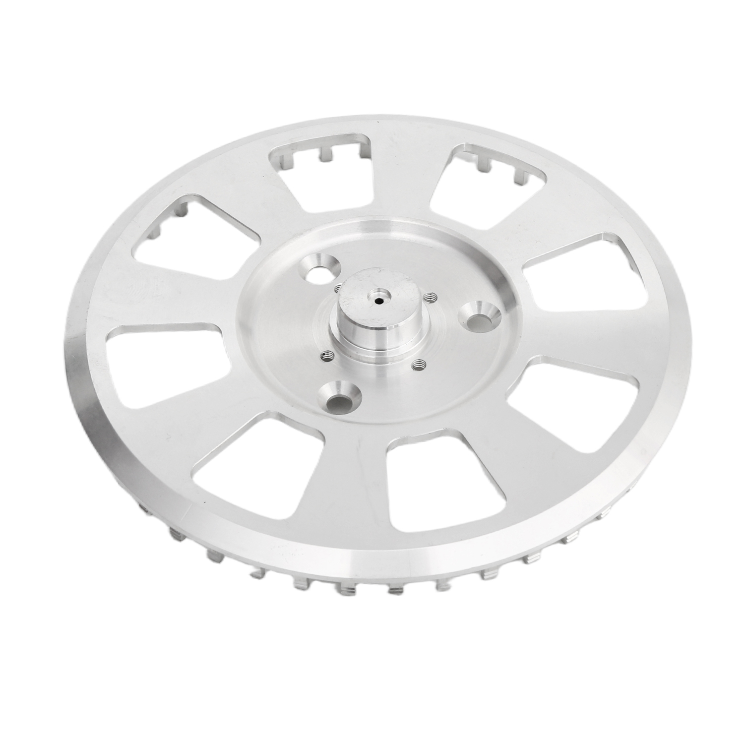
Automotive drive shafts are predominantly manufactured from high-strength carbon and alloy steels, such as 4140, 4340, or 8620. These materials offer the necessary tensile strength and torsional rigidity to handle engine torque, but they present specific machining challenges. Tool wear mitigation and thermal management strategies dictate success during heavy material removal. High-pressure through-tool coolant systems (often exceeding 1000 PSI) blast chips away from the cutting zone and prevent thermal shock to the carbide inserts. Maintaining a consistent cutting temperature extends tool life and ensures dimensional stability across a large batch of parts.
Managing residual stresses is a constant battle when turning alloy steels. The aggressive mechanical action of rough turning introduces stress into the outer layers of the bar stock. If not properly managed, these stresses release during subsequent heat treatment phases like induction hardening or carburizing. This causes the shaft to warp out of tolerance. Experienced machinists mitigate this by optimizing feed rates, utilizing sharp cutting geometries, and leaving precise amounts of stock allowance for the final hard turning passes.
Material Machinability Profile Comparison
| Material Grade | Primary Application | Machinability Rating | Common Challenges in Turning | Tooling Recommendations |
|---|---|---|---|---|
| 4140 Chromoly Steel | Heavy-duty drive shafts, axles | 65% | High tool wear, heat generation, residual stress warping | Coated carbide (CVD), PCBN for hard turning |
| 8620 Alloy Steel | Splined shafts, pinions | 60% | Stringy chips during roughing, requires rigid workholding | PVD coated carbide, high-pressure coolant |
| Aluminum 6061-T6 | EV drive shafts, lightweight propshafts | 120% | Chip control (bird-nesting), material galling on inserts | Polished uncoated carbide, PCD inserts |
| Aluminum 7075-T6 | High-performance/racing drivetrains | 100% | Maintaining surface finish at high surface speeds | PCD inserts, emulsion coolant |
The automotive industry is undergoing a massive shift toward lightweight drivetrains. This is driven primarily by the rapid expansion of Electric Vehicles (EVs) and high-performance hybrid platforms. Reducing rotational mass directly improves battery range, acceleration, and overall vehicle efficiency. As a result, the demand for aluminum CNC turning services has surged. Vendors must adapt their machining strategies to handle aerospace-grade aluminum alloys like 6061-T6 and 7075-T6.
Specific challenges arise in aluminum turning that differ entirely from steel. While aluminum cuts easily, managing chip control is notoriously difficult. The material tends to form long, continuous, stringy chips that wrap around the workpiece or tooling. This causes surface scratches and catastrophic machine crashes. Preventing material galling—where soft aluminum welds itself to the cutting edge—requires highly polished, uncoated carbide or Polycrystalline Diamond (PCD) inserts. Maintaining dimensional stability under high-speed machining conditions demands perfect coolant concentration and precise thermal compensation within the CNC control.
Transitioning a driveshaft design from the prototyping phase to full-scale automotive production requires a manufacturing environment built for continuous operation. Automated bar feeders, gantry loaders, and pallet pools reduce cycle times and minimize human intervention. For shorter transmission shafts, hydrodynamic bar feeders push 12-foot lengths of raw stock through the spindle automatically. This allows the machine to run unattended for hours. For longer, heavier driveshafts, robotic gantry systems load raw billets and unload finished parts with exact precision, pacing the production line perfectly.
Evaluating a vendor's capacity to scale seamlessly involves auditing their workflow architecture. A capable partner utilizes the same CAM programs, tooling strategies, and workholding principles developed during the low-volume prototyping phase and maps them directly onto automated production cells. This seamless transition ensures that the first-article inspection results mirror the quality of the ten-thousandth part coming off the line.
Optimizing unit economics in automotive machining requires a deep understanding of the cost-to-value trade-offs inherent in the turning process. Engineers constantly balance cycle time speed against tool life degradation and surface finish quality. Pushing the machine to its maximum feed rate produces parts faster, but the resulting spike in insert wear increases tooling costs and forces frequent machine stoppages for tool changes. Advanced manufacturers utilize tool life management software integrated into the machine control. This tracks cutting time and automatically swaps to redundant sister-tools before the primary tool fails, maintaining high throughput without sacrificing quality.
When sourcing CNC turning services for high-volume runs, upfront Non-Recurring Engineering (NRE) costs must be weighed against long-term piece price reductions. Investing heavily in custom hydraulic fixturing, dedicated live-tooling heads, and automated robotic end-effectors requires significant initial capital. However, this upfront investment drastically reduces the per-part cycle time and labor burden. It results in a highly competitive unit price over the lifespan of the automotive program.
Relying solely on post-process inspection is insufficient for modern automotive driveshaft production. Automated probing, laser micrometers, and CMM (Coordinate Measuring Machine) verification are mandatory. In-machine spindle probes verify raw material positioning before the first cut and measure critical bearing journals before the part is unclamped. This allows the CNC control to automatically update tool wear offsets in real-time, correcting dimensional drift dynamically.
Statistical Process Control (SPC) integration detects tool wear and dimensional drift before parts fall out of tolerance. By networking digital micrometers and CMM outputs to a centralized quality database, quality engineers monitor process capability indices (Cpk and Ppk). If a specific journal diameter begins trending toward the upper tolerance limit, the SPC system flags the operator to intervene long before a scrap part is produced.
Manufacturing long, precision shafts carries inherent physical risks that must be engineered out of the process.
Risk: Thermal expansion during machining causing out-of-tolerance parts. As the cutting tool generates heat, a long steel shaft expands axially and radially. If machined to nominal dimensions while hot, the part shrinks out of tolerance as it cools.
Mitigation: Implementation of advanced high-pressure coolant strategies directed precisely at the cutting edge to evacuate heat through the chip. Furthermore, utilizing climate-controlled manufacturing facilities ensures that both the machine casting and the workpiece remain at a stable 68°F (20°C) during critical finishing passes.
Risk: Supply chain disruptions and material inconsistencies. Variations in the metallurgical composition of raw bar stock cause unpredictable tool wear and inconsistent heat treatment results.
Mitigation: Establishing robust vendor raw material sourcing networks with strict material traceability. Implementing inventory management systems like Kanban or Just-In-Time (JIT) ensures a continuous flow of certified, uniform material lots. This insulates the production line from external supply shocks.
The automotive supply chain operates on strict regulatory and quality frameworks. IATF 16949 and ISO 9001 requirements apply to Tier 1, 2, and 3 automotive suppliers. IATF 16949 specifically mandates continuous improvement, defect prevention, and the reduction of variation and waste in the supply chain. A machining partner lacking this certification poses an unacceptable risk to OEM production schedules.
Navigating the PPAP (Production Part Approval Process) and FMEA (Failure Mode and Effects Analysis) with your turning partner ensures repeatable quality. A comprehensive Level 3 PPAP submission involves process flow diagrams, control plans, dimensional results, material certifications, and initial process studies. Collaborating closely with the vendor during the FMEA stage identifies potential machining failures—such as steady rest marring or spline runout—and establishes concrete control methods to prevent them from reaching the assembly line.
Take the following actions to secure a reliable manufacturing partner:
Request a detailed capability statement highlighting their specific machine park, including maximum turning lengths, steady rest availability, and live-tooling axis configurations.
Initiate a pilot run for a specific driveshaft variant to physically audit their surface finish quality, concentricity control, and adherence to GD&T callouts.
Audit their PPAP documentation, SPC data collection methods, and automated in-line probing routines to verify their capacity for high-volume repeatability.
Review their raw material sourcing network and traceability protocols to confirm long-term supply chain stability.
A: Advanced CNC turning centers equipped with high-resolution glass scales and thermal compensation routinely hold diametrical tolerances of +/- 0.005 mm. Total runout and concentricity can be maintained within 0.010 mm across the length of the shaft, depending on the L/D ratio and the application of programmable steady rests.
A: The process involves aggressive rough turning to establish the near-net shape, followed by stress-relief heat treatment. The part then undergoes semi-finishing, induction hardening of critical journals, and finally, hard turning or burnishing to achieve the final dimensions and required surface finish without secondary grinding.
A: Live tooling allows the lathe to perform milling, drilling, and tapping operations while the part remains clamped in the spindle. This done-in-one approach eliminates the need to move the shaft to a separate milling machine. It removes refixturing errors and ensures perfect alignment of splines and cross-holes.
A: Yes, high-strength aerospace-grade alloys like 6061-T6 and 7075-T6 are increasingly used in EV and performance vehicle driveshafts to reduce rotational mass. When engineered with appropriate wall thicknesses and proper spline engagement, aluminum shafts handle high torque while significantly improving drivetrain efficiency.
A: Manufacturers prevent deflection and warping by utilizing programmable tailstocks and hydraulic steady rests to support the workpiece. They manage thermal expansion through high-pressure coolant application and utilize intermediate stress-relief heat treatments to stabilize the material structure before final finishing passes.
A: Scaling from prototype to high-volume production typically takes 8 to 16 weeks. This timeline accounts for finalizing the CAM programming, designing and manufacturing custom hydraulic workholding, integrating robotic automation, and completing the rigorous PPAP validation required by automotive OEMs.
A: At a minimum, the manufacturer must hold ISO 9001 certification. For direct supply to automotive OEMs or Tier 1 integrators, IATF 16949 certification is strictly required. This standard ensures the vendor has robust defect prevention, continuous improvement, and supply chain risk management systems in place.


