English ![]()

No. 7, Tianyang 6th Road, Dongfang Community, Songgang Street, Bao'an District, Shenzhen, Guangdong, China(518100)
Views: 136 Author: Site Editor Publish Time: 2026-06-20 Origin: Site
Designing for custom metal fabrication bridges the critical gap between imagination and physical reality. Every bend, hole, and tolerance specification dictates exactly how efficiently raw material transforms into a functional finished product. Unfortunately, unoptimized digital models rapidly drain project resources before production even begins. Poorly planned geometries require excessive prototyping cycles and generate heavy material waste. These engineering oversights inevitably push back launch dates and severely shrink profit margins.
Integrating practical manufacturing realities early solves these costly problems. Proper planning minimizes scrap, speeds up final assembly, and ultimately accelerates your time-to-market. This guide equips engineers and procurement teams with actionable design rules. You will learn practical evaluation frameworks to ensure complete manufacturing certainty. We cover fundamental principles, specialized industry requirements, and common engineering pitfalls. By the end, you will know exactly how to align your digital files with factory-floor capabilities for a flawless production run.
Design for Manufacturability (DFM) directly influences project costs, yield rates, and lead times.
Standardizing bend radii and hole clearances prevents structural weaknesses and tooling conflicts.
Specialized applications, such as electronic enclosures, require distinct tolerances and material considerations.
Partnering with an experienced fabrication service early in the design phase significantly reduces revision risks.
Design for Manufacturability (DFM) represents the crucial bridge between an engineering concept and a profitable product line. We must first examine the problem framing surrounding unoptimized models. Unoptimized designs consistently lead to excessive machining time. For instance, an engineer might unknowingly place a flange too close to a critical mounting hole. The press brake operator must then create a slow, custom setup to avoid distorting the part during the bend. This slows down production significantly. Furthermore, forcing improper bends causes severe material fatigue. Repeated stress on poorly designed joints causes premature failure in the field. High rejection rates and unhappy end-users inevitably follow.
Adopting rigorous DFM principles shifts your cost-to-value ratio favorably. Strict adherence to standard tooling controls your production budgets from day one. Every custom punch, specialized V-die, or non-standard tool adds hundreds of dollars to your initial setup costs. Establishing realistic tolerances keeps part prices predictable and stable. You avoid paying aerospace-level prices for commercial-grade enclosures just because a CAD software defaulted to a tight tolerance.
Manufacturing certainty remains the ultimate goal for any procurement team. You must effectively bridge the gap between an idealized CAD blueprint and factory-floor realities. Software assumes materials bend perfectly and stretch uniformly. Factory floors, however, deal with physical springback, material grain variations, and tool wear. An experienced custom metal fabrication partner anticipates these physical variables long before the laser cutter turns on.
Scalability criteria require careful attention during the initial drafting phase. Ensuring a design can transition smoothly from low-volume prototyping to high-volume production without major re-engineering saves months of delay. You achieve true scalability by following these specific steps:
Standardize your material gauges across multiple product lines to leverage bulk purchasing power.
Eliminate secondary operations like manual grinding or spot welding wherever functionally possible.
Design self-locating features, such as tabs and slots, to speed up downstream assembly times.
Validate standard tooling availability with your vendor before finalizing the digital flat pattern.
Understanding the physical rules governing metal forming separates amateur designs from professional, production-ready files. Bend radii rules of thumb stand out as the most critical starting point. You should maintain a consistent bend radius across the entire part whenever possible. This simple practice dramatically minimizes setup times. Press brake operators load one set of tools to complete all bends sequentially. Mixing multiple radii on a single part forces the operator to stop the machine, swap out heavy tooling, and recalibrate the back-gauge. This adds unnecessary labor costs to every single unit produced.
Note: A standard practice is to keep the inside bend radius equal to or greater than the material thickness to prevent cracking.
Next, consider hole placement and clearances carefully. You must maintain specific minimum distance requirements between holes, edges, and bends. Bending metal stretches the outer surface and compresses the inner surface. If a hole sits too close to the bend line, the forming process inevitably pulls it out of shape. The hole stretches into an oval. This ruins alignment for subsequent assembly steps and prevents fasteners from seating correctly.
Relief cuts and notches are equally important for structural integrity. Implementing proper bend reliefs prevents tearing when bending adjacent flanges. When you fold two sides of a metal box upward, the material trapped in the corner bunches up and collides. A relief cut removes this problematic extra material beforehand. It allows the metal to stretch naturally, resulting in crisp, clean corners.
Finally, material selection dictates overall process compatibility. Evaluating how different alloys behave under physical stress, laser cutting, and welding prevents catastrophic failures. Stainless steel provides excellent strength and corrosion resistance. However, it requires significantly higher press brake tonnage to form. Aluminum cuts quickly and dissipates heat remarkably well. Yet, it cracks easily if you bend it sharply against its natural grain. Knowing these traits ensures your design matches the chosen manufacturing process.
Review this standard clearance table to guide your next design:
| Feature Type | Standard Minimum Rule | Primary Purpose |
|---|---|---|
| Hole to Edge Distance | 1.5x Material Thickness | Prevents outer edge bulging and weakening. |
| Hole to Bend Line | 2.5x Material Thickness + Bend Radius | Prevents hole distortion during the forming cycle. |
| Bend Relief Width | 1.5x Material Thickness | Prevents material tearing at the flange corner. |
| Bend Relief Depth | Material Thickness + Bend Radius | Relieves concentrated stress in adjacent bends. |
Electronic components demand highly unique protective features and distinct environmental considerations. Designing custom sheet metal bending parts for electronics requires stringent tolerances to house delicate printed circuit boards safely. Thermal and ventilation allowances keep sensitive internal components cool under heavy processing loads. You must design strategic perforations and louvers to direct airflow efficiently. However, you cannot compromise the structural integrity of the chassis. Always place ventilation cutouts away from load-bearing corners and structural mounting points.
Electromagnetic Interference (EMI) shielding acts as a strict regulatory requirement for most commercial devices. You ensure tight seams and proper overlap to block escaping radiation. Choosing appropriate materials is essential for electronic compliance. Aluminum, galvanized steel, and copper-plated alloys perform exceptionally well for EMI shielding purposes. Maintaining physical contact between mating metal parts prevents electromagnetic leaks.
Tip: When designing enclosures for electronics, incorporate self-clinching fasteners (like PEM nuts) early in the CAD model to guarantee reliable PCB mounting points without secondary welding.
Surface finish and grounding need simultaneous planning to avoid late-stage manufacturing failures. Coatings like anodizing and powder coating act as strong electrical insulators. If you cover the entire part in powder coat, grounding wires will fail to connect. You must specify clear masking areas on your engineering drawings. Masking maintains bare metal contact points during the finishing process. This precise planning ensures proper electrical conductivity where necessary, keeping the final product safe and compliant.
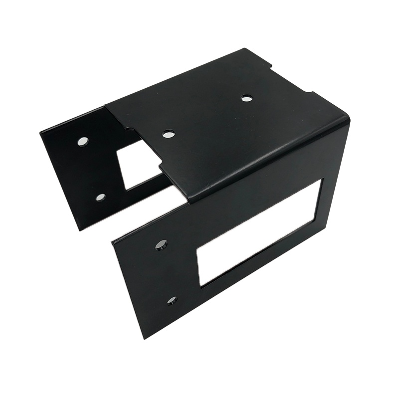
Precision bending and strategic fastener placement ensure reliable assembly for electronic enclosures.
Even seasoned engineers occasionally encounter specific implementation risks when transitioning models to the shop floor. Over-tolerancing stands out as the most common and expensive issue. Demanding tighter tolerances than functionally necessary acts as a massive cost multiplier. When you specify a tolerance of ±0.005 inches on a simple cosmetic bracket, you force the manufacturer to slow down their machines. They must measure every single part manually. They often discard perfectly functional parts simply because they miss an arbitrary dimensional mark by a fraction of a millimeter. Standard commercial tolerances usually suffice for most standard applications.
Ignoring material grain direction frequently ruins rigid metal parts. Sheet metal originates from a heavy rolling mill. This intense rolling process gives the metal a distinct, linear grain direction. Bending parallel to the grain leads to severe micro-fractures, especially in rigid metals like 6061 aluminum or high-strength steel. You should always orient your flat patterns so that critical bends run perpendicular to the material grain.
Overcomplicating flat patterns causes massive production bottlenecks. Avoid designing nested features impossible to unfold in standard software. Do not rely on complicated multi-axis bending if standard 3-axis equipment can accomplish the same functional goal. Complex, multi-step setups invite human error and increase the risk of dimensional drift across large production batches. Keep the geometry simple, flat, and intuitive.
Tip: Always design with the manufacturer's available tooling inventory in mind; specifying non-standard punches significantly increases lead times and setup costs.
Choosing the right manufacturing partner dictates the ultimate success or failure of your project. You need a highly capable custom sheet metal fabrication service to bring your optimized designs to life efficiently. Begin by assessing technical capability alignment. Review the vendor's equipment list carefully against your specific design requirements.
Do they possess modern fiber laser cutting machines capable of handling thick plate?
Do their CNC press brakes offer enough tonnage for your chosen alloy?
Do they maintain in-house hardware insertion machines for your PEM nuts?
DFM support and feedback matter immensely during vendor selection. A credible vendor proactively flags manufacturability issues before they become expensive mistakes. They suggest cost-saving modifications, such as changing a corner relief or standardizing a hole size, before cutting any metal. They act as an active extension of your engineering team, rather than just a passive order-taker.
Quality control and compliance separate professional manufacturers from unreliable amateurs. Verify their internal inspection protocols early in the conversation. Look for active ISO certifications. Ask about their automated optical inspection (AOI) tools or coordinate measuring machines (CMM). These rigorous systems ensure consistent batch quality from the very first prototype to the final production unit.
Note: The cheapest quote often masks hidden costs in poor quality or delayed lead times. Evaluate vendors based on comprehensive overall value, including consistent reject rates, communication speed, and proactive engineering support.
Shortlisting logic requires a methodical, step-by-step approach. Follow these next-step actions to select the best partner:
Request a comprehensive capability and equipment list to match your exact design requirements.
Ask for a sample run of a complex bend or difficult tolerance to verify their physical accuracy.
Review their standard quality inspection reports to ensure full data transparency.
Initiate a small-scale pilot project before requesting a highly detailed, line-item quote for mass production.
Effective custom metal fabrication design is a delicate balance between idealized functional requirements and harsh manufacturing realities. Creating a successful part requires deep respect for physical material limits, machine capabilities, and tooling constraints. By standardizing bend radii, respecting grain direction, and planning for proper clearances, you eliminate the most common production hurdles.
Adopting these foundational principles lowers your procurement risks significantly and ensures highly predictable product rollouts. You reduce wasted material, cut down on revision cycles, and keep your production budgets fully under control. When you design with manufacturability in mind from day one, you build a much stronger, more profitable product line.
We encourage you to audit your current CAD files against these proven rules. Review your flat patterns and tolerance callouts today. Alternatively, consult a fabrication expert for a comprehensive DFM review before your next launch. Taking action now guarantees better physical products and stronger overall profit margins tomorrow.
A: Standard commercial tolerances typically fall around ±0.015 to ±0.030 inches for bends and cuts. Precision applications might require tighter tolerances, such as ±0.005 inches. Tighter tolerances demand slower production speeds and specialized tooling, which significantly increases costs. Always specify the loosest tolerance your functional requirements allow to keep manufacturing budgets under control.
A: Material thickness directly dictates the minimum allowable bend radius and the required machine tonnage. Thicker materials resist forming heavily. They require massive press brake force to achieve the desired angle. If you try to force an overly tight bend radius on thick material, the outer edge stretches too far, fractures, and ultimately fails.
A: Relief cuts prevent material tearing near bend zones. When you bend two adjacent flanges to form a corner, the metal in that junction compresses tightly and binds. A relief cut removes this problematic material beforehand. This gives the adjacent sides enough room to fold upwards without warping or snapping the surrounding structure.
A: You should engage a fabrication partner as early as possible. Involving them during the initial CAD modeling phase allows for critical DFM optimization. They can suggest standardized tooling, recommend better material yields, and identify geometries prone to failure. Early collaboration prevents expensive design revisions and keeps your product launch strictly on schedule.


