
English ![]()

No. 7, Tianyang 6th Road, Dongfang Community, Songgang Street, Bao'an District, Shenzhen, Guangdong, China(518100)
Views: 0 Author: Site Editor Publish Time: 2026-08-10 Origin: Site
Engine builders face a strict set of mechanical constraints. Emission standards, lightweighting targets, and extreme combustion pressures push component designs to their absolute limits. You have to manufacture engine parts to micro-inch tolerances just to keep the assembly from tearing itself apart under load. The core problem is balancing geometric precision and surface finish with scalable production, repeatable consistency, and short lead times across complex engine geometries. Navigating the procurement and engineering of these components requires a hard look at CNC machining capabilities. You need to evaluate milling and turning configurations, material-specific tooling strategies, and quality assurance frameworks. This guide breaks down the exact machine setups, cutting strategies, and inspection protocols required to produce high-performance automotive engine parts that survive real-world thermal and mechanical stress.
Axis-to-Application Matching: Aligning part complexity with machine capability (e.g., utilizing 3-axis for flat components versus 5-axis for organic engine geometries) is critical for optimizing hourly rates and setup costs.
Comprehensive Process Selection: Integrating both CNC milling and CNC turning is essential for full engine assembly production, ensuring optimal manufacturing for both prismatic blocks and cylindrical components like pistons and valves.
Material-Driven Machinability: The choice between cast iron, aerospace-grade aluminum, and titanium directly dictates tooling wear rates, thermal management strategies, and overall cycle times.
DfM as a Cost and Lead Time Lever: Strict adherence to Design for Manufacturability (DfM) principles—such as standardizing internal radii and minimizing part re-orientation—drastically reduces unnecessary setups, accelerates prototyping, and mitigates production risks.
Verifiable Compliance: Vendor evaluation must extend beyond machine availability to prioritize verifiable quality control (CMM inspection, SPC) and automotive-specific certifications (IATF 16949).
Internal engine components operate under severe friction and immense combustion pressure. Defining acceptable deviation limits for these parts forms the baseline of automotive manufacturing. Crankshafts, camshafts, pistons, and valve guides require tight dimensional control to maintain proper oil clearances and prevent catastrophic failure. A deviation of just a few microns in a journal bearing leads to rapid wear or engine seizure.
Surface roughness (Ra) dictates friction reduction and fluid dynamics. Cylinder walls require specific cross-hatch patterns to retain oil, while valve seats demand mirror-like finishes to ensure proper gasket sealing efficacy. Establishing baseline requirements for geometric dimensioning and tolerancing (GD&T) is mandatory. Engine blocks and cylinder heads rely on strict GD&T callouts for flatness, parallelism, and true position to ensure all mating surfaces align perfectly during final assembly.
Standard Automotive Engine Machining Tolerances
| Component Feature | Typical Tolerance Range | Surface Finish (Ra) | Primary GD&T Control |
|---|---|---|---|
| Crankshaft Main Journals | +/- 0.0001 inches | 4 to 8 microinches | Cylindricity, Runout |
| Cylinder Bore Diameters | +/- 0.0002 inches | 15 to 25 microinches | True Position, Perpendicularity |
| Valve Guide Bores | +/- 0.00015 inches | 8 to 16 microinches | Concentricity |
| Engine Block Deck Height | +/- 0.001 inches | 30 to 50 microinches | Flatness, Parallelism |
Leveraging advanced machining for rapid prototyping allows engineers to validate engine component designs before committing capital to expensive casting or forging dies. Machining parts from solid billet material provides accurate functional testing data. Once the prototype passes validation, the transition to low or medium-volume production must occur without capability degradation, tolerance drift, or a loss of production efficiency.
Implementing Statistical Process Control (SPC) requirements ensures batch-to-batch consistency. Automotive compliance relies heavily on maintaining acceptable Cp and Cpk capability indices. Assessing machine tool rigidity dictates the success of these metrics. Heavy cuts on tough materials require massive cast-iron machine bases to dampen vibration. Thermal stability requirements dictate the use of spindle chillers and linear scale feedback systems to compensate for heat expansion during continuous, high-efficiency production runs.
Machine the initial prototype from solid billet to bypass tooling delays and validate the CAD model.
Establish baseline cutting parameters, including spindle speed, feed rate, and depth of cut, during the prototyping phase.
Implement automated tool wear monitoring to detect insert degradation before it impacts part dimensions.
Track Cp and Cpk metrics across the first 50 production units to verify process stability.
Lock the CAM program and fixturing setup to prevent unauthorized alterations during volume production.
Differentiating CNC turning from milling focuses on lathe operations required for symmetrical, high-RPM engine parts. The workpiece rotates at high speeds while a stationary cutting tool removes material. This process manufactures pistons, engine valves, crankshaft journals, and camshaft profiles. These specific components demand exceptional concentricity and minimal runout tolerances to prevent vibration at high engine speeds.
Evaluating the efficiency of multi-tasking mill-turn centers reveals significant production advantages. These machines combine the rotational capabilities of a lathe with the multi-axis milling capabilities of a machining center. This hybrid approach reduces setups for complex cylindrical parts that require both turning and off-center milling, such as a crankshaft with offset rod journals or a camshaft with intricate lobe profiles. Consolidating operations into a single machine reduces handling time and eliminates stacking positional errors.
Analyzing the capabilities of standard 3-axis milling setups highlights their distinct cost-efficiency. In a 3-axis configuration, the cutting tool moves across the X, Y, and Z linear axes simultaneously. While it cannot reach undercuts or machine multiple sides without manual repositioning, it remains highly effective for specific tasks. Identifying ideal automotive use cases controls production costs.
Engine builders frequently utilize 3-axis CNC machining for flanges, oil pan perimeters, simple brackets, and flat-profile engine mounts. Calculating the cost-to-benefit ratio for these low-complexity geometries shows that avoiding multi-axis machines saves significant hourly rates. When multiple setups are not required, 3-axis centers provide rapid material removal, excellent rigidity for face milling, and precise hole-making capabilities at a fraction of the cost.
Understanding the introduction of the rotary axis (A-axis or B-axis) explains the leap in efficiency for certain engine components. A 4-axis machine adds rotation around one of the linear axes, allowing for continuous machining around a cylindrical profile or indexing to reach multiple sides of a prismatic part. This capability fundamentally changes how complex parts are fixtured and processed.
Deploying 4-axis CNC machining for gearbox housings, camshafts, and multi-sided engine blocks significantly reduces fixturing stages. Instead of manually flipping a heavy engine block four times to machine different faces, the rotary table positions the part automatically. Evaluating the impact of this setup reduction shows a drastic decrease in overall cycle time and manual labor costs. Keeping the part clamped in a single fixture ensures tight datum alignment accuracy across all machined faces.
Differentiating between 3+2 positional machining and simultaneous 5-axis interpolation dictates the approach to highly complex geometries. In 3+2 machining, the two rotary axes lock into position, and the machine operates as a standard 3-axis mill on that specific plane. Simultaneous 5-axis machining moves all five axes at once, keeping the cutting tool continuously engaged at the optimal angle relative to the part surface.
Engineers rely on 5-axis CNC machining for complex precision parts such as cylinder heads with intricate porting, turbocharger impellers, and complex intake manifolds. Weighing the conceptual trade-offs is necessary. Higher hourly machine rates are easily offset by the complete elimination of multiple fixturing stages. This automation reduces human error during part handling and delivers superior surface finishes on organic shapes by utilizing shorter, more rigid cutting tools.
Utilize simultaneous 5-axis motion for smooth, continuous toolpaths on turbo impellers.
Apply 3+2 positional indexing to machine deep angled holes in cylinder heads efficiently.
Leverage shorter cutting tools in 5-axis setups to eliminate chatter and improve surface finish.
Reduce total lead time by consolidating operations that would otherwise require multiple 3-axis machines.
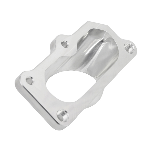
Evaluating the weight reduction benefits of aluminum explains its dominance in modern engine blocks and cylinder heads. Aluminum significantly lowers the overall vehicle weight, improving fuel efficiency and handling dynamics. Its excellent thermal conductivity helps dissipate combustion heat rapidly. Analyzing machinability ratings reveals specific challenges. While generally easy to cut, aggressive milling generates heat that causes thermal expansion, potentially pushing tight-tolerance bores out of spec. Machining 6061 aluminum often allows for speeds exceeding 10,000 RPM and feed rates above 200 inches per minute, provided the machine spindle can handle the torque.
Specific tooling requirements prevent built-up edge (BUE), where soft aluminum welds itself to the cutting tool flutes. Utilizing polished carbide inserts or polycrystalline diamond (PCD) tooling ensures clean chip evacuation. High-volume flood coolant is mandatory to keep the workpiece dimensionally stable and flush chips out of deep pockets.
Meeting the extreme durability and fatigue resistance requirements for crankshafts, connecting rods, and traditional engine blocks requires ferrous metals. Forged high-strength steels and nodular cast iron withstand the brutal reciprocating forces of internal combustion. Managing tooling wear rates becomes a significant engineering hurdle. The abrasive nature of cast iron, particularly due to its graphite flakes, degrades standard carbide rapidly. Cutting 4340 steel requires dropping surface speeds down to 250-400 SFM depending on the hardness, utilizing TiAlN coated carbide inserts to withstand the extreme heat generated at the cutting edge.
Optimizing cutting speeds and feeds maintains tool life. Selecting appropriate high-pressure coolant strategies clears abrasive chips from the cutting zone and prevents thermal shock to the cutting inserts. In some cast iron applications, dry machining with a strong air blast is preferred to prevent the graphite dust from turning into a thick, abrasive sludge in the coolant tank.
Assessing use cases in high-performance, motorsport, and extreme-stress engine applications highlights the need for titanium and advanced superalloys like Inconel. Titanium valves and specialized connecting rods offer an unmatched strength-to-weight ratio and exceptional heat resistance. Evaluating the severe cost implications is necessary before specifying these materials for production.
Titanium possesses poor thermal conductivity, meaning the heat generated during machining transfers directly into the cutting tool rather than the chip. This results in slow material removal rates (MRR) and necessitates specialized carbide tooling with specific geometries and coatings. Ti-6Al-4V limits cutting speeds to roughly 150-200 SFM. Trochoidal milling strategies, which maintain a constant radial chip thickness, are mandatory to prevent the tool from rubbing and work-hardening the material surface. Rigid machine setups, low cutting speeds, high feed rates, and high-pressure through-spindle coolant are absolute requirements to prevent catastrophic tool failure.
Deploy PCD tooling for high-silicon cast aluminum to maximize tool life.
Utilize ceramic or heavily coated carbide inserts for aggressive cast iron milling.
Implement trochoidal milling toolpaths to manage heat when machining titanium alloys.
Monitor spindle loads constantly when cutting superalloys to detect premature tool wear.
Strict adherence to Design for Manufacturability (DfM) principles dictates how efficiently a part moves from CAD to finished product. Standardizing internal radii to match standard end-mill sizes is a primary rule. If a pocket requires a custom-ground tool to reach a non-standard corner radius, lead times and tooling costs escalate immediately. Avoiding deep, narrow pockets is equally important, as they cause severe tool deflection, resulting in tapered walls and poor surface finishes. When designing pockets, maintain a length-to-diameter (L:D) ratio of under 3:1 for the cutting tool. Anything deeper requires relieved shank tooling and significantly reduced feed rates to prevent chatter.
Designing for standard tool lengths eliminates the need for expensive custom tooling extensions. Deep cavities require long tools, which are prone to vibration during machining. By optimizing the part geometry to allow for shorter, more rigid tools, you accelerate overall production lead times, improve surface finish quality, and extend the lifespan of the cutting inserts.
Incorporating dedicated fixturing points or clamping tabs into the initial CAD design solves major workholding challenges for complex, heavy engine blocks. Instead of struggling to grip irregular cast surfaces, engineers use these sacrificial tabs to secure the part rigidly during heavy roughing operations. These tabs are simply machined off during the final finishing pass.
Minimizing part re-orientation is the ultimate goal of effective fixturing. Every time a part is unclamped, moved, and re-clamped, you introduce the risk of positional error. Designing the component so that the maximum number of features can be reached in a single setup maintains strict datum alignment across multiple machining operations. This approach pairs perfectly with 4-axis and 5-axis machining strategies.
Ensure corner radii are slightly larger than the radius of the intended cutting tool to prevent tool engagement shock.
Limit pocket depths to no more than four times the diameter of the standard end mill.
Add threaded tooling holes to the CAD model specifically for zero-point clamping systems.
Design flat, parallel datum surfaces early in the process to simplify initial vice clamping.
Heat generation during aggressive material removal poses a severe risk to automotive components. Warping or dimensional shifts in tight-tolerance parts can render an entire batch useless. Residual stress from previous casting or forging processes often releases during machining, causing the part to twist or bow unexpectedly. Mitigating this requires a multi-step approach.
Enforcing proper coolant application is the first line of defense against thermal distortion. Specifying stress-relief annealing prior to final finishing passes allows the metal to stabilize after heavy roughing. Optimizing CAM tool paths to distribute heat evenly across the part, rather than concentrating it in one deep pocket, further controls dimensional shifting. Leaving a small amount of stock material for a final, light finishing pass ensures the final dimensions remain true.
Defining mandatory inspection protocols separates reliable suppliers from risky vendors. Coordinate Measuring Machines (CMM) provide the absolute truth regarding geometric accuracy, utilizing touch probes to verify complex 3D profiles. Surface profilometers confirm that Ra values meet the strict friction requirements of internal engine components. Non-destructive testing (NDT), such as ultrasonic or magnetic particle inspection, identifies hidden internal flaws or micro-cracks before the part reaches assembly.
Verifying supplier credentials is non-negotiable in the automotive sector. Auditing traceability documentation ensures every material heat lot is accounted for. First Article Inspection (FAI) reports validate that the manufacturing process is capable of meeting all print specifications before volume production begins. Strict adherence to ISO 9001 and the automotive-specific IATF 16949 standards guarantees that the supplier operates under a rigorously audited quality management system.
Mandate roughing, resting, and finishing cycles for parts prone to residual stress warping.
Require full 5-axis CMM reporting for all critical engine block datum points.
Implement ultrasonic NDT for forged connecting rods to detect internal voids.
Demand complete material test reports (MTRs) to verify alloy composition and heat treatment.
Export your engine component CAD files in STEP format and verify all GD&T callouts are attached to the native models.
Submit a Request for Quote (RFQ) that explicitly demands a Design for Manufacturability (DfM) review prior to toolpath generation.
Require the supplier to provide a First Article Inspection (FAI) report utilizing a 5-axis CMM for all critical datum points.
Establish a clear Statistical Process Control (SPC) baseline by defining the required Cpk values for high-wear rotational features.
A: Critical engine components, such as crankshaft journals, valve guides, and piston bores, typically require tolerances between +/- 0.0001 inches (2.5 microns) and +/- 0.0005 inches (12.7 microns). Non-critical features like external brackets or oil pan flanges allow looser tolerances around +/- 0.005 inches. Achieving these tight tolerances requires rigid machine setups and strict thermal control.
A: While 5-axis machines have higher hourly operational rates, they reduce costs by eliminating multiple manual setups. Complex parts like cylinder heads are machined in one or two operations rather than five or six. This reduces manual labor, eliminates the need for multiple custom fixtures, and cuts down total production lead time.
A: CNC turning is utilized specifically for symmetrical, cylindrical components that rotate during engine operation. Parts like pistons, valves, camshafts, and crankshafts require turning to achieve perfect concentricity and minimal runout. Milling is reserved for prismatic parts like engine blocks, or for adding off-center features to turned parts.
A: Aluminum 6061 and 7075 are frequently used for billet cylinder heads due to their excellent machinability and high strength-to-weight ratios. Cast aluminum alloys, such as A356, are common for production heads. These alloys provide superior thermal conductivity, which is essential for dissipating combustion heat quickly and efficiently.
A: In 3+2 machining, the two rotary axes index the part to a fixed angle, and the machine cuts using the 3 linear axes. It is ideal for drilling angled holes in engine blocks. Simultaneous 5-axis machining moves all five axes at once, keeping the tool perfectly perpendicular to curved surfaces, making it essential for machining complex turbocharger impellers.
A: Preventing thermal distortion requires managing heat generation. This is achieved by utilizing high-pressure flood coolant, optimizing cutting feeds and speeds, and using sharp, application-specific tooling. Performing heavy roughing passes, followed by a stress-relief annealing process before the final light finishing pass, ensures the block remains dimensionally stable.
A: At a minimum, a reliable supplier should hold ISO 9001 certification for general quality management. For direct automotive supply chains, IATF 16949 is the required standard. It dictates stringent requirements for defect prevention, supply chain variation reduction, and continuous improvement specific to automotive manufacturing.


